
FAT-130 · Lesson 2 of 12 · 20 min
Voltage, current, resistance and Ohm's law
The first homework Gerry hands out is a single sheet with a strobe's data sheet stapled to it. 'Everything you need to know about this strobe electrically is on that page,' he tells the trainees. 'The voltage range it works over, how much current it draws at each candela setting, and whether that current changes with voltage. By the end of tonight you'll be able to work out the rest yourself.' This lesson covers the three basic electrical quantities and the relationship between them that every fire alarm calculation is built on: Ohm's law, and its companion, the power equation.
Voltage: the push
Voltage is the difference in electrical potential between two points, the push that drives charge through a circuit. It is measured in volts. A fire alarm panel's notification output might sit at 27 volts when the panel is on primary power with its batteries charged, and fall towards 20 or 21 volts at the end of a long period on battery. Voltage is always measured between two points: across a battery's terminals, across an appliance's terminals, or from a conductor to ground. A voltmeter connected across a component reads the voltage that component sees.
In a circuit, voltage is used up along the way. The battery or power supply provides it, the wires use a little of it, and the appliances use the rest. The voltage lost along a wire is the voltage drop, and in fire alarm work it is the quantity that most often decides whether a design works. The voltage that reaches the last appliance on a circuit is the source voltage minus every drop along the way.
Current: the flow
Current is the rate at which charge flows past a point, measured in amps. One amp is a large current in fire alarm terms; most devices are rated in milliamps. A smoke detector on an addressable loop might draw a fraction of a milliamp in standby, a relay module a few tens of milliamps, a horn-strobe on its highest setting a couple of hundred milliamps. In a series circuit the same current flows through every part; in parallel branches, the current divides, and the total is the sum of the branch currents. This is why the current on a notification circuit is the sum of the currents of all the appliances on it.
Fire alarm power is direct current, which flows in one direction, from the positive terminal through the load and back to the negative terminal. The panel's primary supply is alternating current from the building, which the power supply converts to DC. Alternating current reverses direction many times a second, and it has its own measurements, which are covered in lesson 6 where they apply to primary power.
Resistance: the opposition
Resistance is a material's opposition to current, measured in ohms. Copper wire has a low resistance, which grows in proportion to the wire's length and shrinks as its cross-section grows; lesson 5 covers wire resistance in detail. Resistors are components made to have a known resistance, and fire alarm circuits use them as end-of-line devices so that the panel can supervise the wiring. Appliances and detectors are not simple resistors, because they contain electronics that draw a current set by their design rather than by Ohm's law, but the wiring that feeds them behaves exactly like a resistor.
Ohm's law
Ohm's law connects the three quantities. The voltage across a resistance equals the current through it multiplied by the resistance. Rearranged, it gives the current when the voltage and resistance are known, or the resistance when the voltage and current are known.
In fire alarm work the most common use of Ohm's law is the voltage drop along a pair of wires: the current the appliances draw, multiplied by the resistance of the wires that carry it. A circuit carrying 1.5 amps through wiring with a total resistance of 2 ohms loses 1.5 × 2 = 3 volts. A second common use is the supervisory current through an end-of-line resistor: 24 volts across a 4,700-ohm resistor drives about 5 milliamps.
# Ohm's law in three forms
def volts(I, R): return I * R
def amps(V, R): return V / R
def ohms(V, I): return V / I

print(f"drop across wiring: 1.5 A x 2.0 ohm = {volts(1.5, 2.0):.2f} V")
print(f"supervisory current: 24 V / 4700 ohm = {amps(24, 4700) * 1000:.2f} mA")
print(f"wire resistance from a reading: 1.2 V at 0.8 A = {ohms(1.2, 0.8):.2f} ohm")drop across wiring: 1.5 A x 2.0 ohm = 3.00 V supervisory current: 24 V / 4700 ohm = 5.11 mA wire resistance from a reading: 1.2 V at 0.8 A = 1.50 ohm
Power
Power is the rate at which energy is used, measured in watts. In a DC circuit, power equals voltage times current. Combined with Ohm's law, it can also be written in terms of current and resistance, which shows that the power wasted in a wire grows with the square of the current: doubling the current on a circuit quadruples the heat in its wiring.
Fire alarm technicians use power mainly in three places. Power supplies are rated in watts or in amps at a voltage, and the load on them must stay within that rating. Speakers in voice systems are set to taps measured in watts, and the amplifier must be large enough for the sum of the taps. And the power drawn from the building's primary supply, including the power used to charge the batteries, determines the size of the branch circuit.
Constant-current, constant-power and resistive loads
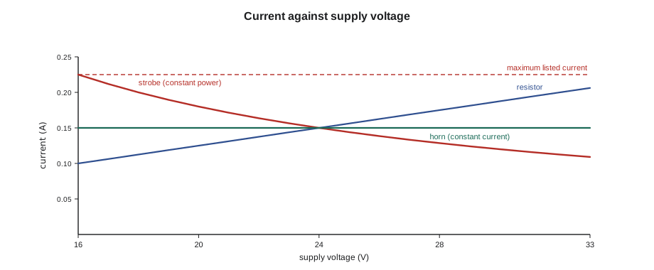
Ohm's law describes a resistor perfectly. Fire alarm appliances are more complicated, and the difference matters. A resistor draws less current when its voltage falls. Most modern strobes do the opposite: they contain a switching circuit that charges a capacitor to a fixed energy for each flash, so they behave roughly like constant-power loads, and as the voltage falls, their current rises. A strobe that draws 150 milliamps at 24 volts might draw close to 200 milliamps at 16 volts. Electronic horns behave more like constant-current loads. This is why appliance data sheets list current at more than one voltage, and why a voltage drop calculation that uses the current at 24 volts can underestimate the real current at the end of a weak circuit.
Under the listing standards for notification appliances, 24-volt appliances are listed to operate over a regulated range, commonly 16 to 33 volts, and the maker publishes the maximum current the appliance draws anywhere in that range. That maximum is the figure to use in calculations, unless the panel and appliance makers publish a method that accounts for how current changes with voltage.
# How three kinds of load respond as the supply voltage falls (illustrative)
R_load = 160.0          # a resistor that draws 0.150 A at 24 V
P_strobe = 24 * 0.150   # a strobe modelled as constant power (3.6 W)
I_horn = 0.150          # a horn modelled as constant current
print(" volts  resistor  const-power  const-current   (amps)")
for v in (27, 24, 20, 16):
print(f" {v:3d} {v / R_load:.3f} {P_strobe / v:.3f} {I_horn:.3f}")volts resistor const-power const-current (amps) 27 0.169 0.133 0.150 24 0.150 0.150 0.150 20 0.125 0.180 0.150 16 0.100 0.225 0.150
The output shows why designers use the maximum listed current: at 16 volts the constant-power model draws a third more current than it does at 24 volts, which would increase the voltage drop on the wires, which would lower the voltage further. Real appliances are somewhere between these models, and the data sheet's maximum covers them.
Reading an appliance data sheet
Sasha's homework strobe is a typical multi-candela horn-strobe. Its data sheet lists the candela settings, from 15 to 110, and for each one the maximum current with DC and with full-wave rectified power, the horn's current at its high and low volume settings, and the operating voltage range. It also says whether the appliance can be synchronized with others on the same circuit and which sync modules or panels are compatible. To find the current for an appliance, a technician reads the row for the candela setting actually installed, adds the horn current if the horn is on the same circuit, and uses the figure for the type of power the panel provides. A mistake common enough that Gerry warns about it every year is reading the 15-candela current for an appliance set to 75 candela.
| Setting | Strobe current (mA, max, 16 to 33 V DC) | Horn current, high volume (mA) |
|---|---|---|
| 15 cd | 88 | + 22 |
| 30 cd | 143 | + 22 |
| 75 cd | 264 | + 22 |
| 110 cd | 354 | + 22 |
Worked problem
The weak strobe at Willowbank
During an annual test at Willowbank School, a strobe at the end of a corridor flashes, but visibly more slowly than the others, and its horn sounds weak. Sasha measures 15.2 V at its terminals with the circuit in alarm, while the panel's output reads 24.1 V. The circuit carries 1.62 A. What is the resistance of the wiring, and what does the reading tell her?
Show solution
- The voltage lost on the wiring is 24.1 − 15.2 = 8.9 V.
- By Ohm's law, the wiring resistance is 8.9 / 1.62 = about 5.5 Ω, much more than a circuit of this length should have.
- 15.2 V is below the 16 V minimum of the appliance's listed range, so it is not guaranteed to work properly.
- A resistance that high suggests a poor connection or a splice somewhere along the circuit, or a run much longer or thinner than the drawing shows.
Answer: Sasha measures the voltage at each appliance back towards the panel. The voltage drops 6 V across a single wire nut in a junction box above the corridor ceiling, where the conductors are corroded. Once it is replaced, the last strobe reads 22.4 V.
Ohm's law at the panel
Ohm's law also explains what a panel sees on its outputs. A notification output that is rated 3 amps is protected by a current limit or a fuse sized for that rating. If the appliances on the circuit draw more than the rating, the output's protection trips, the panel reports a fault and the appliances stop. If a short develops, the resistance of the circuit falls to almost nothing, and the current Ohm's law predicts is far beyond the rating, so the protection acts at once. In both cases, the technician's first measurement is the circuit's current in alarm with a clamp meter, compared with the rating and with the calculation.
The power equation explains why the trade cares about heat in panels and supplies. A power supply that delivers 6 amps at 24 volts delivers 144 watts to its loads, and it wastes some more as heat inside the cabinet, because no supply is perfectly efficient. A supply that is 85 percent efficient draws about 170 watts from the line to deliver 144, and the difference, about 25 watts, warms the cabinet. Panels mounted in small, unventilated closets, or next to a boiler, run hot, and their batteries age faster. The installation manual's limits on ambient temperature are there for a reason.
Gerry ends the evening with a rule of thumb that he says has saved him more time than any formula: when a circuit misbehaves, measure the voltage where the power starts and the voltage where it is used, under load. The difference is the drop, Ohm's law turns it into a resistance, and the resistance tells you where to look.
Sasha tries the rule on a training board at the end of the class. With the board's notification circuit in alarm, she reads 26.8 volts at the panel and 24.1 volts at the last horn-strobe, with 0.9 amps flowing. The 2.7 volts lost corresponds to 3 ohms of wiring, far more than the board's few metres of wire should have, and she finds the instructor's deliberately loosened terminal in under a minute.
Common mistakes
MistakeUsing the strobe current at 24 V for a circuit whose last appliance will see 17 V.
InsteadUse the maximum listed current over the operating range.
MistakeReading the current for the wrong candela setting.
InsteadUse the row for the setting actually installed.
MistakeForgetting that a measured drop includes both conductors.
InsteadCurrent goes out on one wire and back on the other; both have resistance.
MistakeMeasuring voltage with the circuit idle.
InsteadThe drop only appears when current flows; measure in alarm.
MistakeTreating power and current as the same thing.
InsteadWatts are volts times amps; a supply's rating may be given either way.
Summary and key terms
- Voltage pushes, current flows and resistance opposes.
- Ohm's law: V = I × R, so the drop in a wire is the current times the wire's resistance.
- Power is V × I, and the heat in a wire grows with the square of the current.
- Strobes behave roughly like constant-power loads: their current rises as voltage falls.
- Listed 24 V appliances work from 16 to 33 V; calculations use the maximum listed current.
- Read the data sheet row for the setting actually installed.
- Voltage
- The electrical push between two points, in volts.
- Current
- The flow of charge, in amps or milliamps.
- Resistance
- Opposition to current, in ohms.
- Ohm's law
- The relationship V = I × R.
- Power
- The rate of using energy, in watts; V × I in a DC circuit.
- Voltage drop
- The voltage lost across the wiring or a connection when current flows.
Practice problems
Work each problem on paper first, then reveal the answer to check.
A circuit carries 0.9 A through wiring of 3.0 Ω. What is the voltage drop?
Show answer
2.7 V.
24 V is applied across a 3,900 Ω end-of-line resistor. What current flows?
Show answer
About 6.2 mA.
A power supply delivers 3 A at 24 V. What power is that?
Show answer
72 W.
A strobe draws 3.6 W. About what current does it draw at 18 V?
Show answer
0.2 A (3.6 / 18).
If the current on a circuit doubles, what happens to the heat in its wiring?
Show answer
It quadruples.
Lesson quiz · 5 questions
Score 60% or more to complete this lesson.
Create a free account to save your progress, take quizzes and earn a certificate.