
ELEC-330 · Lesson 8 of 12 · 27 min
Timers, counters, comparisons and data handling
Real control problems involve more than switching outputs on and off according to inputs. A conveyor should stop five seconds after the last box passes, a star-delta starter must change over after the motor accelerates, a packing machine must close a case after 24 bottles, a pump must not run if the tank level is below 20 %, and an alarm should only sound if high pressure persists for three seconds. PLC timers, counters, comparison and math instructions make these behaviours easy to program and change. This lesson covers on-delay, off-delay and retentive timers, up and down counters, comparison and limit instructions, arithmetic and data movement, data types and their pitfalls, and how these instructions combine to build typical machine functions such as sequences, batching and alarm handling.
Timer basics
A PLC timer measures how long a condition has been true. Each timer has a preset (the target time), an accumulated value (elapsed time), and status bits: enable (EN, rung true), timer timing (TT) and done (DN, accumulated value has reached the preset). In tag-based systems, a timer is a structure (for example Timer1.PRE, Timer1.ACC, Timer1.DN); in IEC 61131-3 terms, timers are function blocks with an input (IN), a preset time (PT), an output (Q) and an elapsed time (ET). Time bases and resolutions vary, commonly 1 ms, and presets are given in milliseconds or as time values such as T#5s.
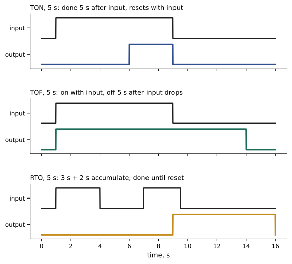
- On-delay timer (TON): starts timing when its rung becomes true; the done bit turns on after the preset elapses, and everything resets as soon as the rung goes false. Used for delays before starting, alarm confirmation delays and debouncing.
- Off-delay timer (TOF): the output turns on immediately when the rung goes true, and stays on for the preset time after the rung goes false. Used for run-on times, such as keeping a fan running after a heater stops, or a conveyor running until it clears.
- Retentive timer (RTO or TONR): accumulates time while its rung is true, holds the accumulated value when the rung goes false, and must be reset explicitly. Used to total run time for maintenance scheduling or cumulative process times.
Worked problem
An alarm confirmation delay
A pressure switch may chatter briefly during normal operation. The high-pressure alarm should activate only if the switch stays on continuously for 3 s, and the pump should then stop. Describe the logic.
Show solution
- Rung 1: XIC High_Pressure_Switch drives a TON named HP_Delay with preset 3,000 ms.
- Rung 2: XIC HP_Delay.DN latches (OTL) HP_Alarm, so the alarm stays until acknowledged even if pressure falls.
- Rung 3: XIC Alarm_Reset_PB AND XIO High_Pressure_Switch unlatches (OTU) HP_Alarm, so it can be reset only when pressure is normal.
- In the pump run rung, add XIO HP_Alarm in series, so the alarm stops the pump.
Answer: A TON filters brief chatter; a latched alarm with conditional reset stops the pump and requires acknowledgement. Momentary pulses under 3 s reset the timer and do not alarm.
Counters
Counters count rising edges (false-to-true transitions) of their rung, regardless of how long the rung stays true:
- Count up (CTU): increments the accumulated value on each rising edge; the done bit turns on when the accumulated value reaches the preset.
- Count down (CTD): decrements the accumulated value on each rising edge.
- Reset (RES): clears the accumulated value and status bits.
An up counter and a down counter sharing the same accumulated value can track items entering and leaving an area, such as parts in a buffer or vehicles in a parking garage. Counters may also have overflow and underflow bits. The counting rate is limited by the scan: an input pulse must be on for at least one scan and off for at least one scan to be counted, so fast pulses from encoders or high-speed lines need high-speed counter modules (Lesson 6).
Worked problem
Counting bottles into cases
A photoelectric sensor detects bottles at up to 8 per second. Each case holds 24 bottles. When 24 are counted, a gate closes for 1.5 s while the full case moves, and counting restarts. The PLC scan is 6 ms and each bottle blocks the sensor for at least 40 ms. Can a standard input count reliably, and how is the logic arranged?
Show solution
- Check timing: 8 bottles per second means a gap of 125 ms between bottles; each on time of 40 ms and off time of about 85 ms are both much longer than the 6 ms scan, so a standard input and counter work.
- Rung 1: XIC Bottle_Sensor drives CTU Bottle_Count with preset 24.
- Rung 2: XIC Bottle_Count.DN drives a TON Gate_Timer with preset 1,500 ms and energizes Gate_Close.
- Rung 3: XIC Gate_Timer.DN resets (RES) Bottle_Count, which also resets the timer on the next scan as Bottle_Count.DN goes false.
Answer: Standard I/O is sufficient because pulses last many scans. The counter triggers a timed gate cycle and then resets itself.
Comparison instructions
Comparison instructions test numerical relationships and act as conditional contacts: equal (EQU), not equal (NEQ), greater than (GRT), greater than or equal (GEQ), less than (LES), less than or equal (LEQ), and limit (LIM), which is true when a value lies between two limits. They compare timer and counter values, analog measurements, setpoints and counts. Examples include starting a fill pump when level is less than 20 %, stopping it when greater than 90 % (with the gap providing hysteresis to prevent rapid cycling), triggering a warning when motor current is between 90 % and 100 % of rating, and activating outputs at specific timer values to build simple timed sequences from one timer.
Comparing analog or floating-point values for exact equality is unreliable, because measured values rarely equal a setpoint exactly; use greater-than or limit tests with a tolerance band instead.
Math and data movement
PLCs provide arithmetic (add, subtract, multiply, divide, modulo, square root, trigonometric functions), compute or expression instructions that evaluate formulas, and data movement (move, masked move, copy, fill, file and array operations). Typical uses include scaling analog values (Lesson 9), calculating flow totals and averages, converting units, computing production rates and efficiencies, and storing recipes and setpoints. In structured text, calculations are written as expressions, such as Flow_Total := Flow_Total + Flow_Rate * Scan_Time / 3600.0, which is often clearer than chains of ladder math instructions.
Data types and their pitfalls
Every value in a PLC has a data type, and mistakes with types cause subtle bugs:
| Type | Size | Range or use |
|---|---|---|
| BOOL | 1 bit | On or off states |
| INT | 16 bits | −32,768 to 32,767 |
| DINT | 32 bits | About −2.1 billion to 2.1 billion |
| REAL | 32 bits | Floating point, about 7 significant digits |
| TIME and timer structures | Varies | Durations, timer presets and elapsed times |
| STRING | Varies | Text, such as batch identifiers |
- Overflow: adding to an INT beyond 32,767 wraps around to negative values or faults the processor, depending on the PLC. A production counter in an INT that counts beyond 32,767 parts will fail; use DINT.
- Integer division truncates: 7 ÷ 2 = 3 in integer arithmetic. Scale before dividing or use REAL.
- Floating-point precision: a REAL has about seven significant digits, so adding small increments to a very large total (such as adding 0.001 m³ each scan to a total of 10,000,000 m³) may stop changing the total at all; use larger types, periodic accumulation or separate integer and fractional totals.
- Type conversion: moving a REAL into an INT rounds or truncates, and moving out-of-range values causes errors.
Building sequences
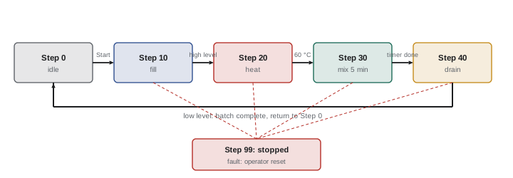
Many machines run in sequences: a press cycle (clamp, press, hold, release, eject) or a tank batch (fill, heat, mix, drain). Simple sequences can be programmed with a step number held in an integer, using comparisons (EQU Step 10) to enable each step's outputs, and transitions that move to the next step when conditions are met (for example a timer done or a sensor on). This "state machine" pattern is easier to understand, troubleshoot and extend than webs of latches. Sequential function charts (SFC) provide a graphical form of the same idea. Every sequence needs defined behaviour for stops, faults and restarts: what happens if the stop button is pressed in step 30, and how does the operator safely return the machine to its starting position?
Timers and counters in troubleshooting
Timers and counters appear constantly when troubleshooting machines. A sequence that seems stuck may be waiting for a timer that will never complete because its rung keeps resetting, for example a TON enabled by a sensor that flickers. A counter that never reaches its preset may be missing pulses because the input is shorter than the scan or because the sensor sees the gaps between products as one long object. When a machine behaves differently from expectations, watch the accumulated values online: they show exactly what the logic is doing and whether inputs are behaving as expected.
Using timers for diagnostics
Timers are also valuable diagnostic tools. A watchdog timer on each step of a sequence detects when a step takes longer than it should, for example a cylinder that should extend within 2 s, and raises a specific alarm such as "Clamp cylinder did not extend", pointing the electrician directly to the problem instead of leaving a stopped machine with no explanation. Similarly, comparing the actual time between events with the expected time reveals slow valves, dragging mechanisms or low air pressure before they cause stoppages. Well-designed programs include these watchdogs for every motion and sequence step.
Run-time totals from retentive timers and cycle counts from counters support maintenance planning, for example scheduling lubrication or replacing a component after a set number of operations. Recording these values on the HMI or in a historian helps maintenance teams move from reactive repair to planned maintenance.
Finally, remember that changing timer presets and counter values can change how a machine behaves in ways that affect safety and quality. Presets should be adjusted only with authorization and documented like other program changes.
Example: a fill-and-drain sequence
Consider a small tank that fills to a high level, heats to a temperature, holds for a set time, then drains. A step-number program uses an integer Step. In step 0 (idle), pressing Start sets Step to 10. In step 10, the fill valve opens until the high-level switch turns on, then Step becomes 20. In step 20, the heater runs until the temperature exceeds the setpoint, then Step becomes 30. In step 30, a TON times the hold period, keeping the heater cycling under temperature control, and when it is done Step becomes 40. In step 40, the drain valve opens until the low-level switch turns on, then Step returns to 0 and a batch counter increments. Each output is driven by one rung that checks which steps need it, for example the fill valve rung examines EQU Step 10. A fault in any step, such as a fill taking longer than expected, moves Step to 99, which turns off all outputs and raises an alarm until an operator resets it.
Written this way, the sequence is easy to read on the HMI (the current step number and its description), easy to troubleshoot (the step shows exactly where the machine is waiting), and easy to extend with additional steps.
Common mistakes
MistakeUsing a TON where the output must stay on after the input drops.
InsteadUse a TOF for run-on functions.
MistakeForgetting to reset retentive timers and counters.
InsteadAdd explicit reset logic.
MistakeCounting pulses shorter than the scan with standard inputs.
InsteadUse high-speed counter inputs.
MistakeTesting analog values for exact equality.
InsteadUse ranges with tolerance or hysteresis.
MistakeStoring large totals in INT tags.
InsteadUse DINT or appropriate types and check for overflow.
Summary and key terms
- Timers have presets, accumulated values and status bits; TON delays on, TOF delays off, RTO accumulates.
- Counters count rising edges; CTU, CTD and RES track counts, limited by scan time.
- Comparison instructions act as conditional contacts; use hysteresis and tolerances.
- Math and move instructions scale, total and manage data; structured text suits formulas.
- Data types matter: overflow, integer division and floating-point precision cause bugs.
- Step-number sequences are clearer than webs of latches and need defined fault behaviour.
- Timers, counters and comparisons combine to implement alarms, batching and sequences.
- Preset
- The target value of a timer or counter.
- Accumulated value
- The current elapsed time or count.
- Done bit
- A status bit set when the accumulated value reaches the preset.
- TON
- On-delay timer.
- TOF
- Off-delay timer.
- RTO
- Retentive on-delay timer.
- CTU
- Count-up counter.
- Hysteresis
- A gap between on and off thresholds preventing rapid cycling.
- Overflow
- A value exceeding the range of its data type.
- State machine
- Logic organized as numbered steps with transitions.
Practice problems
Work each problem on paper first, then reveal the answer to check.
What three status bits does a typical timer have?
Show answer
EN, TT and DN.
Which timer keeps a fan running after a heater stops?
Show answer
An off-delay timer (TOF).
What happens to a TON when its rung goes false?
Show answer
It resets.
What does a retentive timer do when its rung goes false?
Show answer
It holds its accumulated value until reset.
What do counters count?
Show answer
Rising edges of their rung.
Why use 20 % and 90 % for pump start and stop?
Show answer
Hysteresis prevents rapid cycling.
What is 7 ÷ 2 in integer arithmetic?
Show answer
3.
What happens when an INT counter passes 32,767?
Show answer
It overflows, wrapping or faulting.
Why avoid exact equality with analog values?
Show answer
Measured values rarely equal a setpoint exactly.
What must every sequence define?
Show answer
Behaviour on stops, faults and restarts.
Lesson quiz · 5 questions
Score 60% or more to complete this lesson.
Create a free account to save your progress, take quizzes and earn a certificate.