
ELEC-330 · Lesson 11 of 12 · 24 min
Machine safety circuits and safety controllers
Machines with moving parts can crush, cut, entangle and strike people, and control systems play a central role in preventing these injuries. Emergency stops, guard interlocks, light curtains and two-hand controls only protect people if the circuits behind them are designed so that a single fault, such as a welded contact, a shorted wire or a failed output, cannot defeat the safety function. Ordinary PLCs are not designed for this, which is why machine safety uses safety relays, safety-rated PLCs and carefully designed circuits evaluated against functional safety standards. Electricians install, wire, test and maintain these systems, and must never bypass them. This lesson covers machine risk assessment, the hierarchy of safeguarding, stop categories and emergency stops, safety devices, safety performance levels and architectures, safety relays and safety PLCs, validation and testing, and the legal and ethical duty not to defeat safeguards.
Risk assessment and safeguarding
Machine safety starts with a risk assessment following ISO 12100 (also used for robots in AI-450): identify all hazards over the machine's life cycle, estimate the risk of each from the severity of harm, frequency of exposure, possibility of avoidance and probability of occurrence, and reduce it with inherently safe design first, then safeguards, then information and training. Safeguards include fixed guards, interlocked movable guards, presence-sensing devices (light curtains, laser scanners, safety mats) and enabling devices. The required reliability of the safety-related control system depends on the risk, as described below.
In Canada, CSA Z432 (Safeguarding of machinery) and CSA Z142 (for power presses) are widely referenced, and provincial occupational health and safety regulations require machine guarding and lockout. Employers must ensure safeguards are in place and maintained.
Stop categories and emergency stops
IEC 60204-1 and NFPA 79 define three stop categories:
- Category 0: an uncontrolled stop by immediately removing power to the machine actuators.
- Category 1: a controlled stop with power available to the actuators to achieve the stop, then power removed when stopped (for example a drive ramps down, then power is removed).
- Category 2: a controlled stop with power left available to the actuators.
Emergency stop functions must be Category 0 or 1, must override all other functions, must not restart the machine when reset (a separate start command is needed), and use red mushroom-head actuators on yellow backgrounds with positive-opening contacts that latch until deliberately reset. An emergency stop is a complementary measure for emergencies, not a substitute for proper safeguarding: a guard interlock prevents the hazard automatically, whereas an emergency stop relies on someone reacting in time.
Safety devices
- Guard interlock switches: tongue-actuated, hinge, magnetic coded or RFID-coded switches that detect guard position; coded switches resist defeat with simple tools or magnets. Guard locking devices keep guards closed until hazardous motion has stopped.
- Light curtains and safety laser scanners: detect people entering hazardous areas, with safety distances calculated from the machine's stopping time and the approach speed (ISO 13855).
- Two-hand controls: require both hands on separated buttons, pressed within 0.5 s of each other, keeping hands away from the hazard during dangerous motion.
- Enabling switches: three-position switches used during teaching and setup, where only the middle position allows motion.
- Safe torque off (STO): a function built into many drives that removes the power to the motor's torque-producing switches through a safety-rated circuit, without removing power to the drive itself. STO enables safe stopping without contactors in many applications.
Safety distance
A light curtain or scanner must be placed far enough from the hazard that a person cannot reach it before the machine stops. ISO 13855 gives the formula:
where S is the minimum distance in millimetres, K is the approach speed (2,000 mm/s for distances up to 500 mm; 1,600 mm/s beyond), T is the total stopping time of the machine plus the response time of the safety system, and C is an intrusion allowance based on the detection capability of the device (for a light curtain with resolution d up to 40 mm, C = 8(d − 14) mm).
Worked problem
Light curtain safety distance
A press has a measured stopping time of 180 ms. The light curtain responds in 15 ms and the safety relay in 20 ms. The light curtain resolution is 30 mm. What minimum distance is required?
Show solution
- Total time T = 180 + 15 + 20 = 215 ms = 0.215 s.
- Intrusion allowance C = 8 × (30 − 14) = 128 mm.
- With K = 2,000 mm/s: S = 2,000 × 0.215 + 128 = 430 + 128 = 558 mm.
- Because S exceeds 500 mm, recalculate with K = 1,600 mm/s: S = 1,600 × 0.215 + 128 = 344 + 128 = 472 mm, which is less than 500 mm, so use S = 500 mm (the standard's minimum for this case).
Answer: Mount the light curtain at least 500 mm from the hazard. Stopping time must be measured with a stop-time meter and rechecked periodically, since brakes wear.
Performance levels and architectures
ISO 13849-1 rates safety-related parts of control systems by performance level (PL), from PLa (lowest) to PLe (highest). The required performance level (PLr) for each safety function is determined from the risk assessment using a risk graph considering severity (slight or serious injury), frequency and duration of exposure, and possibility of avoiding the hazard. The achieved PL depends on:
- Category (architecture): B and 1 (single channel, no fault detection, category 1 using well-tried components), 2 (single channel with periodic testing), 3 (two channels so a single fault does not cause loss of the safety function), and 4 (two channels with fault detection such that accumulation of faults is also detected).
- Reliability of components, expressed as mean time to dangerous failure (MTTFd), often calculated from B10d values (the number of operations until 10 % of components fail dangerously) for electromechanical parts.
- Diagnostic coverage (DC): the fraction of dangerous failures detected.
- Common cause failure (CCF) measures, such as separation and diversity.
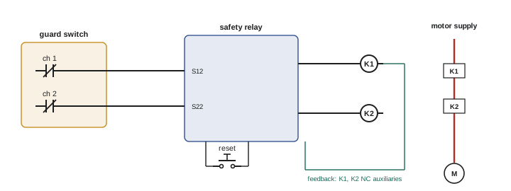
IEC 62061 offers an alternative approach using safety integrity levels (SIL). Many machine safety functions, such as guard interlocks on dangerous machines, require PLd with Category 3 architecture: two independent channels, such as two contacts in a guard switch wired to a safety relay that checks they agree.
Safety relays and safety PLCs
Safety relays are dedicated modules that monitor safety inputs (emergency stops, guard switches, light curtains) through redundant channels, detect faults such as short circuits between channels (cross faults) and welded contacts, and control redundant safety outputs. They check external contactors through feedback loops: the normally closed auxiliary contacts of both contactors must be closed (indicating the main contacts are open) before the relay allows a reset. Safety relays suit machines with a few safety functions.
Safety PLCs (or safety controllers) are programmable controllers certified for safety functions, with redundant processors, self-diagnostics, safety-rated I/O, and certified function blocks for emergency stops, guard monitoring, two-hand control and muting. They handle complex machines with many zones and functions, and can communicate safety data over networks using safety protocols (such as CIP Safety and PROFIsafe) on standard industrial Ethernet. Safety programs are kept separate from standard programs, protected by passwords and signatures, and changes require revalidation.
A standard PLC can monitor safety devices for information and diagnostics, but must not be the only means of performing a safety function.
Validation, testing and maintenance
Safety systems must be validated after installation and after any change: each safety function is tested to confirm that it works and that faults are detected, for example by opening each guard during motion, pressing each emergency stop, interrupting light curtains with test pieces, and simulating faults such as a welded contactor. Results are documented, along with the calculations of PL and safety distances. During operation, periodic tests (daily, before shift, or as specified) confirm safety functions remain effective. Stopping times are measured periodically, as brake wear can lengthen them beyond the distances assumed.
Never defeat safeguards
Bypassed guard switches, taped-down interlocks and jumpered safety relays are a leading cause of serious machine injuries. Reasons given include nuisance trips, the need to observe the process during setup, and production pressure. The right response is to fix the underlying problem: improve the design of the safeguard, provide safe setup modes with enabling devices and reduced speed, or add observation windows. Electricians have a legal and professional duty not to defeat safeguards, and should report bypassed devices. Any temporary bypass for troubleshooting must be controlled by a formal procedure with alternative protection, and removed before the machine is returned to service.
Lockout and safety functions
Safety functions such as interlocks and emergency stops protect people during normal operation, but they are not a substitute for lockout during maintenance. An interlocked guard stops the machine when opened, but the control system could still be faulty, another person could reset it, or stored energy (pneumatic pressure, hydraulic accumulators, gravity, springs, capacitors) could still cause motion. For servicing and maintenance work inside the machine, workers must follow the plant's lockout procedure: isolate all energy sources at their disconnects, apply personal locks, release or block stored energy, and verify zero energy before starting work. Some tasks, such as minor adjustments during normal production, may be performed under alternative measures defined by regulations and the risk assessment, but these must be specifically assessed and documented.
Electricians often design and install the energy isolation points themselves: lockable disconnects for each energy source, pneumatic dump valves that are lockable, and clear labelling of each isolation point on the machine and in the lockout procedure. Good design makes correct lockout easy and quick, which encourages compliance.
Finally, when modifying a machine, check that the change does not affect its safety functions or their validation. Moving a guard, adding an access door, changing a drive or speeding up a machine can all change risks and stopping times, requiring the safety assessment and validation to be updated.
Muting and safe operating modes
Some applications need to let material pass through a light curtain without stopping the machine, for example pallets leaving a palletizer. Muting temporarily suspends the light curtain only while sensors confirm that material, not a person, is passing, using carefully arranged muting sensors and timing. Muting must be designed to standards, indicated with lamps, and validated, because poorly designed muting creates a path for people into hazardous areas. Similarly, setup and maintenance modes that allow motion with guards open must limit speed, require enabling devices, and be selected with a key or access control.
Common mistakes
MistakeUsing a standard PLC as the only safety function.
InsteadUse safety relays or certified safety controllers.
MistakeWiring safety devices single-channel where PLd is required.
InsteadUse the required category, typically dual-channel with monitoring.
MistakeMounting light curtains without calculating safety distance.
InsteadCalculate S = K × T + C with measured stop time.
MistakeAllowing emergency stop reset to restart the machine.
InsteadRequire a separate deliberate start.
MistakeBypassing nuisance-tripping interlocks.
InsteadFix the cause and never defeat safeguards.
Summary and key terms
- Risk assessment and the hierarchy of safeguarding determine safety measures.
- Stop categories 0, 1 and 2; emergency stops are Category 0 or 1 and need a separate restart.
- Safety devices include coded interlocks, guard locking, light curtains, scanners, two-hand controls, enabling switches and STO.
- Safety distance S = K × T + C uses measured stopping time.
- ISO 13849-1 performance levels depend on category, MTTFd, diagnostic coverage and CCF.
- Safety relays and safety PLCs monitor redundant channels, cross faults and contactor feedback.
- Validate and test safety functions regularly, and never defeat safeguards.
- Safeguarding
- Measures protecting people from machine hazards.
- Stop category
- Classification of how a machine stops.
- Positive opening
- Contacts forced open mechanically.
- Light curtain
- An array of light beams detecting intrusion.
- Safe torque off
- A drive function removing torque through a safety circuit.
- Performance level
- The reliability rating of a safety function in ISO 13849-1.
- Category 3
- An architecture where a single fault does not cause loss of the safety function.
- Diagnostic coverage
- The fraction of dangerous failures detected.
- Cross fault
- A short circuit between redundant safety channels.
- Validation
- Testing and documenting that safety functions work.
Practice problems
Work each problem on paper first, then reveal the answer to check.
What is the order of risk reduction?
Show answer
Inherent design, safeguards, information and training.
Describe stop categories 0 and 1.
Show answer
0 removes power immediately; 1 stops under control then removes power.
Why is an emergency stop not a substitute for guarding?
Show answer
It relies on someone reacting in time.
What does STO do?
Show answer
Removes torque-producing power to the motor through a safety circuit.
Compute S for T = 0.1 s, d = 14 mm, K = 2,000.
Show answer
200 + 0 = 200 mm.
What determines achieved PL?
Show answer
Category, MTTFd, diagnostic coverage and CCF measures.
What is a Category 3 architecture?
Show answer
Redundant channels so a single fault does not cause loss of function.
Why do safety relays monitor contactor auxiliary contacts?
Show answer
To detect welded main contacts before reset.
Can a standard PLC perform a safety function alone?
Show answer
No.
Why remeasure stopping times periodically?
Show answer
Brake wear can lengthen them beyond assumed distances.
Lesson quiz · 5 questions
Score 60% or more to complete this lesson.
Create a free account to save your progress, take quizzes and earn a certificate.