
ELEC-330 · Lesson 12 of 12 · 25 min
Troubleshooting PLC systems, cybersecurity and capstone
When an automated machine stops, production stops, and the pressure falls on the maintenance electrician to find the fault quickly and safely. Troubleshooting PLC-controlled systems combines classic electrical skills, reading drawings, measuring voltage and checking devices, with the ability to go online with the PLC, read its diagnostics and follow its logic. Most faults turn out to be in the field: a failed sensor, a loose wire, a tripped breaker, a misadjusted switch or a stuck valve, rather than in the program or the processor. This lesson presents a systematic troubleshooting method for PLC systems, using status indicators and online monitoring, forcing and its dangers, common fault patterns, documentation and change management, the cybersecurity of industrial control systems, and the course capstone project.
A systematic method
Effective troubleshooting follows a repeatable sequence:
- Gather information: what exactly happened, when, and what the operator saw; check the HMI alarm history and PLC fault logs. Many faults are diagnosed in minutes from a clear alarm message.
- Observe the machine and indicators: which outputs are on or off, which sensors show the expected state, and which status LEDs on modules, drives and network devices show faults.
- Divide the system: determine whether the problem lies in the input side (the PLC is not seeing a signal it should), the logic (the PLC sees the inputs but does not turn on the output), or the output side (the PLC turns on the output but the device does not respond).
- Test and measure: confirm with meters and online monitoring, using safe work practices, until the faulty component is found.
- Repair and verify: fix the root cause, test the machine through its cycle, and confirm with the operator.
- Document: record the fault, cause and repair so patterns can be spotted and recurrence prevented.
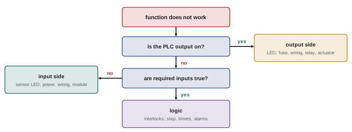
Using status indicators and online monitoring
Input and output module LEDs show the state each point is seeing or driving, providing a quick check at the panel. Going online with programming software shows the program executing in real time: contacts and coils highlight when true, values update, and cross-reference tools find every place a tag is used. To find why an output is off, start at its rung, identify which condition is false, and follow that condition back through the program to an input or internal bit, a technique sometimes called "walking the logic". Many programs include diagnostic rungs or HMI screens showing which permissives are missing, which saves much of this work.
Measurements at the module terminals distinguish field problems from module problems: if 24 V is present at an input terminal (measured against the correct common) but the input LED is off, the module or its configuration is suspect; if the voltage is missing, the problem is in the field device or wiring. For outputs, if the output LED is on but no voltage reaches the terminal, check the module's output power supply and fuse; if voltage is present at the terminal but the device does not work, check the wiring and the device.
Forcing and its dangers
PLC software allows forcing inputs and outputs on or off, overriding the actual field state or program result. Forcing helps test wiring and devices, for example forcing an output to check that a valve operates. It is also dangerous: a forced output can start a motor or move an actuator unexpectedly, and a forced input can make the program believe a guard is closed or a level is safe when it is not. Forces left in place after troubleshooting have caused accidents. Good practice requires following plant procedures for forcing, coordinating with operators, ensuring people are clear of the machine, never forcing safety-related signals, and removing all forces before returning the machine to service; PLCs indicate active forces with LEDs and software flags, which should be checked at handover.
Common fault patterns
| Symptom | Likely causes | Checks |
|---|---|---|
| One input never changes | Failed sensor, misalignment, broken wire, PNP/NPN mismatch | Sensor LED, voltage at terminal, wiring |
| Input flickers | Loose connection, leakage current, noise, target at edge of range | Connections, bleeder resistor, routing, sensor position |
| Output on but device does not act | Blown fuse, open wire, failed coil or solenoid, mechanical jam | Voltage at device, coil resistance, mechanism |
| Several I/O points fail together | Module power, common fuse, failed module, network I/O fault | Module status LEDs, supply voltage, network diagnostics |
| Intermittent stops with no clear cause | Noise, loose terminals, overheating, network errors, supply dips | Trend logs, thermal scan, error counters, power quality |
| PLC in fault mode | Program error, module fault, battery or memory problem | Fault code and log, manufacturer documentation |
Worked problem
Troubleshooting a conveyor that will not start
A conveyor motor does not start when the operator presses Start. The HMI shows no alarms. Online, the Start input turns on when pressed, but the Motor_Run output rung stays false. What next?
Show solution
- Look at the Motor_Run rung: Start is true, but the Downstream_Ready permissive contact is false.
- Cross-reference Downstream_Ready: it is set by an input from a photoelectric sensor that confirms the next conveyor is not full.
- Check that input: its LED is off, although the downstream conveyor is empty.
- At the sensor: the LED shows dark, and the lens is covered with dust; cleaning it restores the beam and the input turns on.
- Verify by running the conveyor through a cycle; record the cause and suggest adding a dirty-lens alarm (many sensors offer a stability or contamination output, or IO-Link diagnostics).
Answer: A dirty photoelectric lens blocked a permissive. Following the logic from the output back to the field input found it quickly, and an improvement prevents recurrence.
Documentation and change management
Accurate documentation is essential for troubleshooting: electrical schematics with wire numbers and cross-references, PLC I/O lists, network diagrams, panel layouts, device data sheets and well-commented programs. When modifications are made, drawings and programs must be updated, or the next person will be misled. Plants use management of change (MOC) procedures for program and hardware changes: changes are proposed, reviewed for safety and operational impact, approved, implemented, tested and documented, with program versions archived so they can be compared and restored. Version-compare tools show exactly what changed between program versions, which is invaluable when a machine behaves differently after a change.
Cybersecurity of industrial control systems
Industrial control systems were once isolated, but networking has exposed many to cyberattacks, and incidents affecting water systems, power grids and manufacturing plants have shown the consequences. Attacks may come through internet-exposed devices, compromised remote access, infected laptops or USB drives, or vulnerable connections to business networks. The ISA/IEC 62443 series provides a framework for securing industrial automation. Practical measures for electricians and maintenance teams include:
- Never connect control networks or devices directly to the internet; use secure remote access through approved gateways with multi-factor authentication.
- Segment networks into zones with firewalls (Lesson 10), keeping control systems separate from business networks.
- Change default passwords on PLCs, HMIs, switches and drives; use role-based accounts.
- Control the use of laptops and removable media in control systems, scanning them for malware.
- Keep firmware and software up to date following vendor and plant procedures, and remove unused services.
- Back up programs and configurations securely so systems can be restored.
- Report unusual behaviour, such as unexplained program changes, unexpected mode changes or unknown devices on the network.
In Canada, the Canadian Centre for Cyber Security publishes guidance for operators of critical infrastructure, and sector regulators (for example in electricity under NERC CIP standards for bulk power systems) set mandatory requirements for some facilities.
Capstone project
The capstone brings the course together. Design, build (on a trainer or in simulation) and document a small automated system, such as a tank filling and mixing station or a conveyor sorting station:
- Electronics and power (Lessons 1 to 3): select and size a 24 V DC supply with protected circuits, calculate voltage drop to the farthest device, and specify suppression for coils.
- Sensors and instruments (Lessons 4 and 5): select and wire discrete sensors with correct PNP or NPN matching, and an analog level or temperature transmitter with a loop resistance check.
- PLC hardware (Lesson 6): select modules with spare capacity and draw the I/O wiring.
- Programming (Lessons 7 to 9): write ladder logic with seal-in starts, interlocks, timers, counters, a step-number sequence, analog scaling, alarms with deadbands, and a PID loop tuned by a step test.
- Networks and HMI (Lesson 10): connect an HMI with an overview screen, alarm list and trend, following high-performance design principles.
- Safety (Lesson 11): implement an emergency stop and a guard interlock with a safety relay, calculate any safety distance, and validate the safety functions.
- Troubleshooting and documentation (Lesson 12): produce drawings, an I/O list and a commented program; then troubleshoot faults inserted by the instructor using the systematic method, and record each diagnosis.
Building troubleshooting skills
Troubleshooting is a skill that improves with practice and reflection. Experienced technicians keep notes on unusual faults and their causes, learn the normal sounds, smells and indicator patterns of the machines they look after, and develop a feel for which components fail most often. They also know when to ask for help: from the machine builder, the PLC or drive manufacturer's support line, or colleagues with different expertise. Asking good questions, with clear descriptions of symptoms, what has been checked and the results, gets faster answers.
Training on simulators and trainers with deliberately inserted faults is an effective way to build confidence, because it allows practice without production pressure or risk. Many plants also hold reviews of significant breakdowns to identify root causes and improvements, using methods such as the five whys or fishbone diagrams.
Predictive maintenance and data
Data from PLCs, drives and sensors can predict failures before they stop production. Trends of motor current, vibration, temperature, cycle times and valve response times reveal gradual degradation: a pump drawing increasing current, a cylinder taking longer to extend, or a bearing running hotter. Condition monitoring systems and analytics platforms analyze these trends and alert maintenance teams. Electricians contribute by installing and maintaining sensors, ensuring data quality, and interpreting alerts with their knowledge of the equipment.
Even simple measures, such as logging cycle times and fault counts on the HMI and reviewing them weekly, reveal patterns that point to the next likely failure. Combined with good documentation and a culture of fixing root causes, they turn troubleshooting from firefighting into planned improvement.
The skills developed in this course, from reading components and sensors to programming, networks and safety, form the foundation for advanced automation work, including motion control, robotics and process control systems, which later courses and on-the-job experience build upon.
When you face an unfamiliar machine, start by finding the drawings, the I/O list and the program, and spend a few minutes understanding its normal sequence before diving into the fault. That investment usually shortens the total troubleshooting time considerably.
Finally, share what you learn. Adding a short note to the maintenance system, updating a drawing, or suggesting a diagnostic alarm after solving a difficult fault helps the next person and steadily improves the reliability of the plant.
The capstone is your chance to practise all of this in a safe setting before applying it on real equipment.
Common mistakes
MistakeAssuming the PLC or program is at fault first.
InsteadDivide the system; most faults are in field devices and wiring.
MistakeLeaving forces active after troubleshooting.
InsteadRemove all forces and check indicators before handover.
MistakeForcing safety-related signals.
InsteadNever force safety signals; follow plant procedures.
MistakeMaking undocumented program changes.
InsteadFollow management of change and update documentation.
MistakeConnecting a PLC to the internet for convenience.
InsteadUse secure, approved remote access and segmentation.
Summary and key terms
- Troubleshoot systematically: gather information, observe, divide, test, repair, verify and document.
- Divide faults into input side, logic and output side using LEDs, measurements and online monitoring.
- Walk the logic from the output back to the missing input or permissive.
- Forcing is useful but dangerous; never force safety signals and remove forces before handover.
- Common faults involve sensors, wiring, fuses, module power, noise and networks.
- Accurate documentation and management of change support reliable maintenance.
- Secure control systems with segmentation, secure remote access, passwords, media control, updates and backups.
- Divide and conquer
- Splitting a system to isolate the faulty section.
- Online monitoring
- Viewing a running PLC program in real time.
- Walking the logic
- Tracing conditions backward from an output to its causes.
- Cross-reference
- A list of every place a tag is used.
- Forcing
- Overriding an input or output state in software.
- Permissive
- A condition that must be true before an action is allowed.
- Management of change
- A process for reviewing and documenting changes.
- Version compare
- A tool showing differences between program versions.
- ISA/IEC 62443
- Standards for industrial automation cybersecurity.
- Network segmentation
- Dividing networks into zones with controlled connections.
Practice problems
Work each problem on paper first, then reveal the answer to check.
List the steps of systematic troubleshooting.
Show answer
Gather information, observe, divide, test, repair and verify, document.
The output LED is on but the valve does not move. Where do you look?
Show answer
Output side: fuse, wiring, voltage at the valve, the valve itself.
24 V is present at an input terminal but the LED is off. What is suspect?
Show answer
The input module or its configuration.
What does walking the logic mean?
Show answer
Tracing from the output rung back to the false condition.
Why is forcing dangerous?
Show answer
It can move machinery unexpectedly or hide unsafe conditions.
Several outputs on one module fail at once. What is likely?
Show answer
Module power, a common fuse or a module failure.
Why update documentation after changes?
Show answer
Otherwise the next troubleshooter is misled.
What does a version-compare tool show?
Show answer
Exactly what changed between program versions.
Name four cybersecurity measures.
Show answer
No internet exposure, segmentation, changed passwords, media control, updates, backups.
What standard series covers industrial automation security?
Show answer
ISA/IEC 62443.
Lesson quiz · 5 questions
Score 60% or more to complete this lesson.
Create a free account to save your progress, take quizzes and earn a certificate.