
ELEC-330 · Lesson 4 of 12 · 26 min
Discrete sensors: proximity, photoelectric and position sensing
Automated machines need to know where parts are, whether guards are closed, when a cylinder has extended, whether a bin is full and whether a person has entered a danger zone. Discrete sensors answer such yes-or-no questions and send an on or off signal to the controller. Electricians install, wire, adjust and troubleshoot thousands of them, and choosing the right sensor and wiring it correctly make the difference between a machine that runs and one that stops every few minutes with false signals. This lesson covers mechanical limit switches, inductive and capacitive proximity sensors, photoelectric sensors and their sensing modes, magnetic and ultrasonic sensors, encoders, sensor output types and wiring including two-wire, three-wire, PNP, NPN and IO-Link, and the selection, mounting and troubleshooting of sensors.
Mechanical limit switches
Limit switches are actuated by physical contact with a lever, roller, plunger or wand, operating internal contacts that may be normally open, normally closed or both. They are rugged, simple to understand, switch AC or DC loads directly, and give positive confirmation of position. Safety-rated versions with positive-opening (direct-opening) contacts force the contacts apart mechanically even if they weld, which is why they are used for guard and safety position monitoring. Limitations include mechanical wear, the need for physical contact, and slower response than electronic sensors.
Inductive proximity sensors
Inductive proximity sensors detect metal objects without contact. An oscillator drives a coil behind the sensing face, creating a high-frequency field; when metal enters the field, eddy currents absorb energy, the oscillation amplitude drops, and the sensor switches its output. Key characteristics:
- Sensing range is short, typically 1 to 40 mm depending on diameter (for example 2 mm for an 8 mm sensor, up to 15 mm or more for a 30 mm sensor), and is specified for a standard mild steel target.
- Non-ferrous metals reduce the effective range: correction factors are typically about 0.4 for aluminum and copper and 0.7 for stainless steel, unless the sensor is a "factor 1" type designed to sense all metals equally.
- Flush (shielded) sensors can be mounted level with surrounding metal but have shorter ranges; non-flush (unshielded) sensors have longer ranges but need clear space around the face.
- They are immune to dirt, oil and water, making them the most common sensor on machines.
Worked problem
Effective range of an inductive sensor
An 18 mm flush inductive sensor has a rated sensing distance of 8 mm. The target is aluminum, with a correction factor of 0.4. Manufacturers recommend operating within 81 % of the corrected range to allow for temperature and tolerance. At what maximum gap should the sensor be mounted?
Show solution
- Corrected range for aluminum: 8 × 0.4 = 3.2 mm.
- Assured operating distance: 3.2 × 0.81 = 2.6 mm.
- Mount the sensor so the target passes within about 2.6 mm, ideally around 1.5 to 2 mm for margin, while avoiding contact.
Answer: No more than about 2.6 mm. For aluminum targets at larger gaps, choose a larger sensor or a factor 1 type.
Capacitive proximity sensors
Capacitive sensors detect changes in capacitance caused by any material with a dielectric constant different from air: plastics, wood, paper, liquids, grain and powders, as well as metals. They are used for level detection through the walls of non-metallic tanks and bins, detecting products in packaging, and sensing non-metallic parts. Most have a sensitivity adjustment that must be set for the material and mounting; they can be affected by humidity, build-up of material on the face and nearby objects, so adjustment and periodic checking are important.
Photoelectric sensors
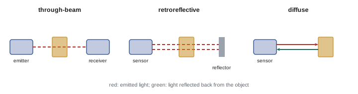
Photoelectric sensors detect objects with a beam of light, usually infrared, red or laser. They sense over much longer distances than proximity sensors and detect almost any material. The main sensing modes are:
- Through-beam: a separate emitter and receiver face each other; the object is detected when it breaks the beam. Longest range (tens of metres), most reliable, unaffected by object colour or surface, but requires wiring at both sides.
- Retroreflective: emitter and receiver are in one housing, with a reflector opposite; the object breaks the beam returning from the reflector. Polarized retroreflective sensors reject reflections from shiny objects that could otherwise fool the sensor.
- Diffuse (proximity): the sensor detects light reflected directly from the object; simple to install but range depends on the object's colour and surface.
- Background suppression: a diffuse sensor that uses triangulation to detect objects only within a set distance, ignoring the background regardless of colour.
- Specialized types include fibre-optic sensors for tight spaces, colour and contrast sensors for registration marks, and laser distance sensors with analog outputs.
Photoelectric outputs are configured as light-operate (output on when the receiver sees light) or dark-operate (output on when the beam is blocked). Excess gain, the ratio of received light to the minimum needed to switch, indicates reliability in dirty environments: a through-beam sensor operating with an excess gain of 10 or more can tolerate considerable lens contamination.
Other discrete sensors
- Magnetic (reed or Hall-effect) cylinder sensors clamp onto pneumatic cylinders and detect a magnet on the piston, confirming extension and retraction.
- Ultrasonic sensors measure the echo time of sound pulses to detect objects regardless of colour or transparency, useful for clear bottles and liquid levels, with discrete or analog outputs.
- Pressure, flow, level and temperature switches change state at a set point (Lesson 5 covers continuous measurement).
- Safety sensors, such as light curtains, safety laser scanners, safety interlock switches with coded actuators and safety mats, are designed and certified for safety functions (Lesson 11).
Encoders
Encoders measure rotation or linear position. Incremental encoders produce pulse trains (often two channels, A and B, in quadrature so the direction can be determined, plus an index pulse once per revolution), with resolutions from tens to tens of thousands of pulses per revolution; the controller counts pulses to track position and calculate speed. Absolute encoders output a unique digital position value (single-turn or multi-turn) that is known immediately at power-up without homing, communicated over interfaces such as SSI or industrial networks. Encoders are used for conveyor tracking, cut-to-length control, motor speed feedback and positioning.
Output types and wiring
Electronic sensors have several output configurations:
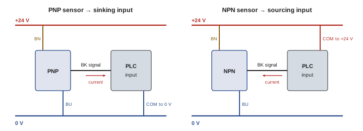
- Three-wire DC sensors have a positive supply (brown), 0 V (blue) and a switched output (black) in the standard colour code. PNP (sourcing) outputs switch +24 V to the load or PLC input; NPN (sinking) outputs switch 0 V. North American and European machines mostly use PNP; some Asian equipment uses NPN. The sensor output type must match the PLC input type (Lesson 2).
- Two-wire sensors are wired in series with the load like a switch, drawing their operating power through the load. They leave a small leakage current when off and a voltage drop when on, which can cause problems with some PLC inputs or when several are wired in series.
- Four-wire sensors may provide both normally open and normally closed outputs, or an output plus an analog or diagnostic signal.
- IO-Link sensors use a point-to-point digital link over standard three-wire cable to an IO-Link master, providing the switching signal plus parameters, diagnostics and measured values. Sensors can be configured remotely, replaced with automatic parameter download, and report contamination or failure before they stop working.
Connectors such as M12 and M8 with standardized pinouts simplify installation and replacement, and prewired cordsets avoid wiring errors at the sensor. Sensor cables should be routed away from power cables and protected from physical damage, and flexing applications need cables rated for continuous flexing.
Selecting sensors
Sensor selection considers the target material and size, the sensing distance, the environment (dirt, coolant, washdown, temperature, explosive atmospheres), speed (switching frequency must exceed the target rate), mounting space, output type and connection, required reliability and diagnostics, and whether the function is safety-related. Ingress protection (IP) ratings such as IP67 or IP69K indicate resistance to dust and water jets. For hazardous locations, sensors must be certified for the classified area, often intrinsically safe with barriers.
Worked problem
Choosing a sensor for a bottle line
A conveyor carries clear plastic bottles at 5 bottles per second. The line must count them. The sensor will be mounted 300 mm from the bottles, with a stainless steel guide rail behind them. Which sensor approach suits this application?
Show solution
- Inductive and capacitive sensors have far too short a range at 300 mm.
- A diffuse photoelectric sensor would struggle: clear bottles reflect little light and the shiny rail behind them could reflect strongly.
- Options: a through-beam sensor across the conveyor (detects the bottle as it slightly attenuates the beam, with sensitivity adjusted), a retroreflective sensor designed for clear objects, or an ultrasonic sensor, which is unaffected by transparency.
- Check speed: 5 bottles per second needs a switching frequency well above 10 Hz; most photoelectric sensors switch at hundreds of hertz or more.
Answer: A clear-object retroreflective sensor or an ultrasonic sensor. Diffuse photoelectric and proximity sensors are poor choices here.
Troubleshooting sensors
Most sensors have LED indicators showing power and output state, which are the first check: if the LED changes when the target is present but the PLC input does not, the problem is in the wiring, the input module, or a PNP/NPN mismatch; if the LED does not change, check the sensor's power, alignment, range and sensitivity, and the target. Measure the output voltage at the sensor and at the input terminal relative to the correct reference. Common problems include loose or damaged connectors, cable damage in flexing areas, misalignment of photoelectric sensors after impacts, dirty lenses, sensors mounted too far from targets, interference between closely mounted sensors, and electrical noise. IO-Link diagnostics can identify many of these remotely.
Sensor installation practices
Correct installation prevents most sensor problems. Mount sensors on rigid brackets that hold their position against vibration and impact, using adjustable brackets so they can be aligned precisely and locked. Protect sensors from being struck by parts or forklifts with guards or recessed mounting. Route cables with strain relief and drip loops, avoid sharp bends, and use cable carriers for moving machine sections. Keep sensors away from welding fields, which can damage inductive sensors unless weld-field immune types are used. Record sensor positions, types and settings in the machine documentation, so replacements can be installed and adjusted quickly.
When adjusting a sensor, check that it switches reliably with the target at the farthest expected position and does not switch on background objects at the nearest position, and that it continues to work as the machine runs at full speed.
Finally, remember that sensor selection affects maintenance for years. Standardizing on a small range of sensor types and connectors across a plant reduces spare parts and helps technicians replace and adjust sensors quickly.
Common mistakes
MistakeUsing rated range for non-ferrous targets.
InsteadApply correction factors and mount within the assured distance.
MistakeUsing diffuse photoelectric sensors for clear or shiny objects.
InsteadUse through-beam, clear-object retroreflective or ultrasonic sensors.
MistakeWiring PNP sensors to sourcing inputs.
InsteadMatch sensor and input types.
MistakePutting several two-wire sensors in series.
InsteadCheck voltage drops and leakage, or use three-wire sensors.
MistakeUsing standard sensors for safety functions.
InsteadUse certified safety sensors and circuits.
Summary and key terms
- Limit switches give rugged, positive position sensing; positive-opening types suit safety monitoring.
- Inductive sensors detect metal at short range; non-ferrous metals need correction factors.
- Capacitive sensors detect almost any material but need adjustment.
- Photoelectric sensors use through-beam, retroreflective, diffuse and background suppression modes.
- Magnetic, ultrasonic, process switches and encoders cover other sensing needs.
- Three-wire PNP or NPN outputs must match the input type; IO-Link adds diagnostics and parameters.
- Select by target, range, environment, speed and safety; troubleshoot with LEDs and measurements.
- Limit switch
- A contact-actuated position switch.
- Positive opening
- Contacts forced open mechanically even if welded.
- Inductive sensor
- A sensor detecting metal through eddy-current losses.
- Correction factor
- A multiplier reducing range for non-steel targets.
- Capacitive sensor
- A sensor detecting changes in capacitance.
- Through-beam
- A photoelectric mode with separate emitter and receiver.
- Background suppression
- A diffuse sensor ignoring objects beyond a set distance.
- Excess gain
- Received light divided by the minimum switching level.
- Quadrature
- Two encoder channels offset by 90° to show direction.
- IO-Link
- A point-to-point digital sensor communication standard.
Practice problems
Work each problem on paper first, then reveal the answer to check.
Why are positive-opening limit switches used for guards?
Show answer
Their contacts open even if welded.
How do inductive sensors detect metal?
Show answer
Eddy currents absorb energy from the oscillator field.
A 12 mm sensor rated 4 mm senses stainless steel (0.7). What is the corrected range?
Show answer
2.8 mm.
What materials can capacitive sensors detect?
Show answer
Almost any: plastics, wood, liquids, powders and metals.
Which photoelectric mode has the longest range?
Show answer
Through-beam.
What do polarized retroreflective sensors reject?
Show answer
Reflections from shiny objects.
What is an incremental encoder's index pulse?
Show answer
One pulse per revolution for referencing.
What do the brown, blue and black wires of a three-wire sensor carry?
Show answer
+24 V, 0 V and the output.
Name two benefits of IO-Link.
Show answer
Remote parameters and diagnostics; automatic replacement setup.
The sensor LED changes but the PLC input does not. Where is the fault?
Show answer
Wiring, input module or PNP/NPN mismatch.
Lesson quiz · 5 questions
Score 60% or more to complete this lesson.
Create a free account to save your progress, take quizzes and earn a certificate.