
ELEC-330 · Lesson 7 of 12 · 25 min
Ladder logic fundamentals
Ladder logic was designed to look like the relay control diagrams electricians already knew, so they could program PLCs without learning a computer language. It remains the most widely used PLC language in North America, especially for machine control and discrete logic, and electricians who can read and modify ladder programs are valuable in any plant. Ladder logic is not the same as a wiring diagram, though: it is executed by the scan, rung by rung, and some behaviours that seem obvious in hard-wired relays work differently in a program. This lesson introduces the IEC 61131-3 programming languages, the basic ladder instructions (examine-if-closed, examine-if-open and output coils), the critical relationship between field devices and program contacts, seal-in and latching circuits, one-shots, the effects of scan order, converting relay diagrams to PLC programs, and good programming and documentation practices.
PLC programming languages
IEC 61131-3 defines standard PLC programming languages:
- Ladder diagram (LD): graphical contacts and coils on rungs between power rails, best for discrete logic and interlocks, and easy for electricians to troubleshoot online.
- Function block diagram (FBD): graphical blocks connected by signal lines, popular for process control and analog logic.
- Structured text (ST): a high-level textual language similar to Pascal, best for calculations, data handling, loops and complex algorithms.
- Sequential function chart (SFC): steps and transitions for sequential processes such as batch operations and machine cycles.
- Instruction list (IL), an assembly-like language, was deprecated in the third edition of the standard.
Most modern PLCs allow mixing languages in one project, so a programmer can use ladder for interlocks, structured text for calculations and SFC for sequences.
Contacts and coils
The basic ladder instructions are:
- Examine if closed (XIC), drawn as a normally open contact: true when its referenced bit is 1 (on).
- Examine if open (XIO), drawn as a normally closed contact: true when its referenced bit is 0 (off).
- Output energize (OTE), drawn as a coil: sets its bit to 1 if the rung conditions before it are true, and to 0 if false.
A rung is true when a continuous path of true instructions exists from the left rail to the output. Contacts in series form AND logic; contacts in parallel branches form OR logic. The same bit can be examined by any number of contacts throughout the program, unlike a physical relay with a limited number of contacts.
The terms "normally open" and "normally closed" for program instructions describe how they examine a bit, not the state of the field device. This is the most important concept for reading ladder logic correctly: an XIC instruction is true when its input is on, regardless of whether the field device is a normally open or normally closed switch.
Field devices and program instructions
Consider a stop pushbutton. For safety, stop buttons are wired normally closed, so that a broken wire or loose terminal stops the machine rather than preventing it from being stopped. With the button not pressed, the NC contact passes current and the PLC input is on (1). Pressing the button opens the contact and the input goes off (0). In the program, the stop input must therefore be examined with an XIC instruction, which is true while the input is on (button not pressed) and false when the button is pressed. Programming it with an XIO instruction, by copying the relay diagram's NC symbol, would make the machine unable to start (or, worse, behave unexpectedly).
| Field device | Wired as | Input when not actuated | Program instruction for "run permitted" |
|---|---|---|---|
| Stop pushbutton | Normally closed | On (1) | XIC (examine if closed) |
| Start pushbutton | Normally open | Off (0) | XIC |
| Overload relay contact | Normally closed (95-96) | On (1) | XIC |
| Guard limit switch | Normally closed, held closed by the guard | On (1) with guard closed | XIC |
| High-level switch for a fault | Normally open, closes on high level | Off (0) | XIO to permit running |
The seal-in (start-stop) circuit
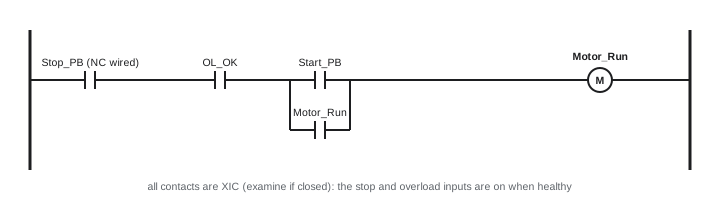
The most common ladder rung is the three-wire start-stop circuit, which mirrors the relay holding circuit from ELEC-310. The motor output is energized when the stop input is on (button not pressed), the overload input is on (not tripped), and either the start input is on or the motor output itself is already on (the seal-in branch).
Worked problem
Tracing a start-stop rung
For the rung shown, trace the output state as the operator presses Start, releases it, then presses Stop. The overload is healthy (OL_OK on) throughout.
Show solution
- Initially: Stop_PB input on (NC, not pressed), Start_PB off, Motor_Run off. Path: Stop true, OL true, but neither branch true, so the output is off.
- Press Start: Start_PB on, so the branch is true and Motor_Run turns on in this scan.
- Release Start: Start_PB off, but the Motor_Run branch contact is now true, so the rung stays true (sealed in).
- Press Stop: Stop_PB input goes off, the first XIC becomes false, and Motor_Run turns off; the seal-in branch drops out.
- Release Stop: Stop_PB is on again, but neither Start nor Motor_Run is on, so the motor stays off until Start is pressed again.
Answer: The rung behaves exactly like a relay three-wire control: momentary start, maintained run, stop overrides, no automatic restart after a stop or power loss.
Latch and unlatch
Latch (set, OTL) and unlatch (reset, OTU) instructions turn a bit on or off and leave it in that state until the opposite instruction executes, even if the rung that set it becomes false. Latched bits are often retentive, keeping their state through power loss, which can be useful for remembering alarms or sequence states, but dangerous for motor outputs: a machine output latched before a power failure could restart automatically when power returns. Many standards and good practices therefore discourage latching outputs that start machinery, and require explicit restart logic.
One-shots
A one-shot (rising edge, ONS or R_TRIG) instruction makes a rung true for exactly one scan when its input changes from off to on. One-shots are used to count events, increment values, trigger a single action per button press, or capture a value at a moment. Without a one-shot, an instruction that adds 1 to a counter while a button is held would add 1 every scan, hundreds of times per second.
Scan order and its effects
Because the program executes top to bottom each scan, the order of rungs affects behaviour. A bit set in one rung is seen with its new value by rungs below it in the same scan, but by rungs above it only in the next scan. Two common problems arise:
- Duplicate (double) coils: if two rungs both use an OTE to the same bit, the last one in the program wins, and the first rung appears to have no effect. Each output should be controlled by one OTE; use branches or intermediate bits to combine conditions.
- Races: logic that depends on the order of updates within one scan can behave differently from an equivalent relay circuit, where everything acts simultaneously. Careful ordering and the use of one-shots avoid surprises.
Physical outputs only change at the end of the scan, so momentary internal changes during the scan do not appear at the outputs.
Converting relay logic
Converting an existing relay control circuit to a PLC is a common project. The steps are: list all inputs (pushbuttons, switches, overload contacts, sensors) and outputs (coils, lights, solenoids) and assign PLC addresses or tags; decide how each input will be wired, keeping stop and safety devices normally closed; replace internal control relays and their contacts with internal bits; replace timer relays with timer instructions (Lesson 8); write each relay rung as a PLC rung, remembering to use XIC for normally closed field devices that must be closed to permit operation; retain hard-wired safety circuits (emergency stops, safety relays) outside the PLC or move them to a safety controller (Lesson 11); and test thoroughly before putting the machine back into service.
Good programming practice
- Use meaningful tag names and add descriptions and rung comments that explain why, not just what.
- Organize programs into routines by function (inputs, alarms, sequence, outputs) or by equipment module, following any plant standard.
- Handle all inputs consistently, for example mapping raw inputs to internal tags with debouncing or validation in one place.
- Include permissives, interlocks and fault handling explicitly, with alarms that tell operators what went wrong.
- Avoid clever code that others cannot follow; the next person to troubleshoot it may be an electrician at 3 a.m.
- Keep backups, document every change with date, author and reason, and use the plant's change management process for online edits.
Online editing, changing a running program, is powerful but risky: a mistake can start or stop machinery unexpectedly. Plants usually require authorization, testing, and coordination with operations before online edits.
Function block diagrams and structured text
Although this lesson focuses on ladder logic, electricians often encounter the other languages. In a function block diagram, the same start-stop logic appears as AND and OR blocks connected by lines, with an SR (set-reset) block or a feedback connection providing the seal-in. Function blocks such as PID controllers, scaling blocks and motor control blocks appear as boxes with labelled inputs and outputs, and FBD makes the flow of signals through a control strategy easy to see. In structured text, the start-stop rung could be written as Motor_Run := (Start_PB OR Motor_Run) AND Stop_PB AND OL_OK; which reads naturally once the syntax is familiar. Structured text is preferred for calculations, loops through arrays, string handling and complex decisions.
Many plants standardize on reusable function blocks (or add-on instructions) for common equipment such as motors, valves and analog inputs. Each block contains the logic for control, interlocks, alarms and HMI interface for one device type, written and tested once and reused hundreds of times. This makes programs consistent and easier to troubleshoot, because every motor behaves the same way and shows the same diagnostic information.
Whichever language is used, the principles of this lesson still apply: understand how field devices are wired, use clear names, avoid duplicate outputs, and design for safe behaviour on stops and power loss.
Practice reading ladder logic
The best way to become comfortable with ladder logic is to read many programs. Start with simple machines, identify each input and output on the drawings, and trace how each output rung uses inputs, internal bits and timers. Ask what happens when each input changes, and what happens on power-up, after an emergency stop, and after a fault. Comparing the program with the machine's actual behaviour builds the intuition needed to troubleshoot quickly. Many PLC trainers and software packages include simulators, which allow practice without hardware or risk to equipment.
With these fundamentals, the next lessons add timers, counters, data handling, analog values and PID, building toward complete machine and process programs.
Common mistakes
MistakeProgramming an NC-wired stop button with an XIO instruction.
InsteadUse XIC: the input is on when the stop is not pressed.
MistakeWiring stop buttons normally open.
InsteadWire stop and safety devices normally closed for fail-safe operation.
MistakeUsing two OTE instructions for the same bit.
InsteadControl each bit from one rung, combining conditions with branches.
MistakeLatching motor outputs that restart after power loss.
InsteadUse seal-in logic and explicit restart conditions.
MistakeEditing running programs without authorization.
InsteadFollow change management and coordinate with operations.
Summary and key terms
- IEC 61131-3 defines ladder, function block, structured text and sequential function chart languages.
- XIC is true when a bit is on; XIO when it is off; OTE writes the rung result to a bit.
- Program instructions examine bit states, not field device types; NC-wired stops use XIC.
- The seal-in rung provides three-wire start-stop control without automatic restart.
- Latch and unlatch hold states; avoid latching outputs that start machinery.
- One-shots act for one scan on a rising edge; scan order matters and duplicate coils cause errors.
- Converting relay logic and good programming practices keep programs safe and maintainable.
- Ladder diagram
- A graphical PLC language resembling relay diagrams.
- Structured text
- A textual IEC 61131-3 language.
- Rung
- One line of ladder logic between the power rails.
- XIC
- Examine if closed: true when the bit is on.
- XIO
- Examine if open: true when the bit is off.
- OTE
- Output energize: writes the rung result to a bit.
- Seal-in
- A branch that holds an output on after the start signal ends.
- Latch
- An instruction that sets a bit until it is unlatched.
- One-shot
- An instruction true for one scan on a rising edge.
- Duplicate coil
- Two outputs writing the same bit, where the last wins.
Practice problems
Work each problem on paper first, then reveal the answer to check.
Name the four main IEC 61131-3 languages in current use.
Show answer
Ladder, function block diagram, structured text, sequential function chart.
When is an XIO instruction true?
Show answer
When its bit is off.
Why are stop buttons wired normally closed?
Show answer
A broken wire then stops the machine.
Which instruction examines an NC stop button for run permission?
Show answer
XIC.
What logic do series and parallel contacts form?
Show answer
AND and OR.
What keeps the motor running after Start is released?
Show answer
The seal-in branch using the motor output bit.
Why are latched motor outputs risky?
Show answer
They may restart automatically after power returns.
What does a one-shot do?
Show answer
Makes a rung true for one scan on a rising edge.
Two rungs write the same coil. Which wins?
Show answer
The last one in the scan.
Name three good programming practices.
Show answer
Meaningful tags, comments, organized routines, backups, change management.
Lesson quiz · 5 questions
Score 60% or more to complete this lesson.
Create a free account to save your progress, take quizzes and earn a certificate.