
ELEC-330 · Lesson 2 of 12 · 26 min
Transistors, thyristors and power electronics
Diodes conduct whenever they are forward biased; transistors and thyristors can be switched on and off by a small control signal. These controllable semiconductors are the building blocks of every electronic control and power conversion device an electrician meets: the transistor outputs of PLCs and sensors, solid-state relays, dimmers, soft starters, battery chargers, UPS inverters, solar inverters and variable frequency drives. Power electronics uses them as fast switches to convert electrical energy efficiently from one form to another. This lesson explains how bipolar transistors, MOSFETs and IGBTs work as switches, how thyristors such as SCRs and triacs control AC power, how converters are built from these devices, how switching losses and heat sinking limit them, and how wide-bandgap devices are changing power electronics.
The transistor as a switch
A transistor has three terminals; a small signal at one terminal controls a larger current between the other two. Transistors can amplify signals, but in control and power work they are used almost entirely as switches, fully on (saturated, with a small voltage drop) or fully off (blocking), because a switch dissipates little power in either state while a partly-on transistor wastes energy as heat.
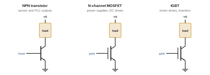
- Bipolar junction transistors (BJTs) have a base, collector and emitter. A small base current controls a collector current about 50 to 300 times larger. NPN transistors switch the load to the negative side (sinking); PNP transistors switch to the positive side (sourcing). BJTs are used in small signal circuits and in many sensor and PLC outputs.
- MOSFETs (metal-oxide-semiconductor field-effect transistors) have a gate, drain and source. A voltage on the gate (typically 5 to 15 V), with almost no steady gate current, controls the drain-source channel, which acts like a small resistance, R_DS(on), when on. MOSFETs switch fast and efficiently at lower voltages and dominate switch-mode power supplies, DC motor controls, battery systems and low-voltage drives.
- IGBTs (insulated-gate bipolar transistors) combine a MOSFET-like gate with a bipolar output stage, handling high voltages (600 to 6,500 V) and large currents with modest on-state voltage drops of about 1.5 to 3 V. IGBTs are the workhorse switches of variable frequency drives, UPS inverters, solar inverters and traction drives.
Sinking and sourcing outputs
The terms sinking and sourcing, central to PLC and sensor wiring (Lessons 4 and 6), come from transistor switching. A sinking output (NPN or N-channel) connects the load to the negative (0 V) side when on; the load's other end connects to +24 V. A sourcing output (PNP or P-channel) connects the load to +24 V when on; the load's other end connects to 0 V. A sinking output must be wired to a sourcing input and vice versa. Mixing them up is one of the most common wiring errors in control panels: nothing happens, or the input is always on.
Thyristors: SCRs and triacs
Thyristors are four-layer semiconductor devices that, once triggered, stay on until the current through them falls to nearly zero. This latching behaviour suits AC power control, where current naturally passes through zero twice each cycle.
- The silicon-controlled rectifier (SCR) conducts in one direction when a gate pulse is applied while it is forward biased, and turns off at the next current zero. SCRs are used in controlled rectifiers for DC drives, battery chargers, and in pairs (back-to-back) in soft starters and heater controllers.
- The triac conducts in both directions and can be triggered in either half-cycle, used in light dimmers, small motor speed controls and solid-state relays for AC loads.
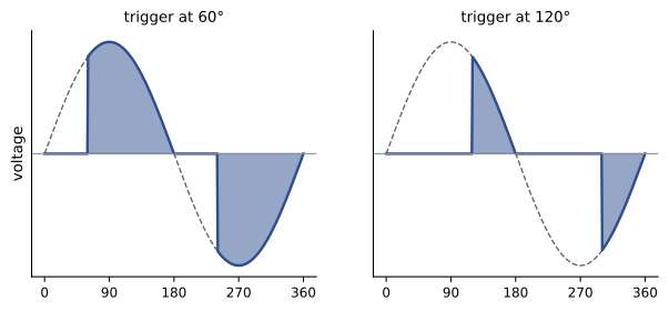
Phase-angle control delays the trigger point in each half-cycle to reduce the average voltage delivered to the load, as in dimmers and soft starters. Burst firing (zero-cross switching) instead switches whole cycles on and off, as in heater controllers, producing less electrical noise but coarser control. Phase-angle control produces harmonics and radio-frequency noise, which is why dimmers and soft starters may need filtering and why soft starters are bypassed by a contactor once the motor reaches speed.
Power conversion
Power electronic converters are built from switches, diodes, inductors and capacitors:
- AC-DC (rectifiers): diode bridges, or SCR or active IGBT front ends that can regulate the DC voltage, reduce harmonics and return energy to the supply (regeneration).
- DC-DC (choppers): buck converters step voltage down, boost converters step it up, and isolated converters use high-frequency transformers. They are found in power supplies, battery chargers and solar optimizers.
- DC-AC (inverters): IGBTs or MOSFETs switch the DC bus to synthesize AC of variable voltage and frequency using pulse-width modulation (PWM), as in drives, UPS systems and grid-tied solar inverters.
- AC-AC: soft starters, cycloconverters and matrix converters control AC directly.
A variable frequency drive combines a rectifier, a DC bus with capacitors, and a PWM inverter. Its output is a train of fast voltage pulses at the DC bus voltage whose average follows a sine wave, with the motor's inductance smoothing the current. These steep-edged pulses cause the reflected wave, bearing current and electromagnetic interference issues covered in ELEC-310.
Pulse-width modulation
PWM controls the average output of a switch by varying the fraction of time it is on, the duty cycle. A 24 V supply switched with a 25 % duty cycle delivers an average of 6 V to a load that smooths it (such as a motor, heater or LED with filtering). Switching frequencies range from a few hundred hertz for heaters to 2 to 16 kHz in motor drives and 50 kHz to over 1 MHz in modern power supplies. Higher switching frequencies allow smaller inductors and capacitors and quieter motors, but increase switching losses and electromagnetic interference.
Worked problem
PWM average voltage and power
A 24 V DC heater element of 12 Ω is controlled by a MOSFET with PWM. What average voltage and power are delivered at 40 % duty cycle? (Power in a resistive load depends on the RMS voltage.)
Show solution
- Average voltage: 0.40 × 24 = 9.6 V.
- Full-on power: 24² ÷ 12 = 48 W.
- With PWM, the element receives full power 40 % of the time: 0.40 × 48 = 19.2 W.
- Note that 9.6² ÷ 12 = 7.7 W would be wrong: heating depends on the RMS voltage (24 × √0.40 ≈ 15.2 V), not the average.
Answer: Average voltage 9.6 V and power 19.2 W. PWM delivers power in proportion to duty cycle for resistive loads.
Losses and heat
Even as switches, semiconductors dissipate power: conduction losses (on-state voltage drop times current, or I² R_DS(on)) and switching losses during each transition from on to off and back, when voltage and current overlap briefly. Losses become heat that must flow through the device package to a heat sink and into the air. Every semiconductor has a maximum junction temperature (commonly 150 °C to 175 °C for silicon), and its life shortens rapidly as temperature rises. This is why drives and soft starters are derated at high ambient temperatures and altitudes, why their cooling fans and heat sink fins must be kept clean, and why enclosures need adequate ventilation or cooling. A blocked fan is one of the most common causes of drive failure.
Worked problem
Estimating heat in a soft starter
A soft starter uses back-to-back SCRs with an on-state drop of about 1.5 V per phase. During a 20 s start, the motor current averages 300 A. Estimate the heat produced during the start, and explain why a bypass contactor is used after starting.
Show solution
- Power per phase: 1.5 V × 300 A = 450 W.
- Three phases: 3 × 450 = 1,350 W.
- Energy during the start: 1,350 W × 20 s = 27,000 J.
- If the SCRs stayed in circuit at a running current of 100 A, they would dissipate 3 × 1.5 × 100 = 450 W continuously; a bypass contactor eliminates this loss and the need for large heat sinks.
Answer: About 1.35 kW during the start (27 kJ in total). Bypassing after the start saves around 450 W of continuous heat and extends the starter's life.
Protection of power semiconductors
Semiconductors fail quickly when overloaded: unlike a copper conductor, a junction can be destroyed by an overcurrent lasting milliseconds. Protection includes fast-acting semiconductor fuses (marked aR or gR) that clear faults before the device fails, electronic current limiting and desaturation detection in drive gate drivers, snubber circuits (resistor-capacitor networks) and metal-oxide varistors (MOVs) that limit voltage spikes, and thermal sensors on heat sinks. When replacing fuses in drives, soft starters or rectifiers, use exactly the type specified by the manufacturer; an ordinary fuse of the same rating may not protect the semiconductors.
Wide-bandgap semiconductors
Silicon carbide (SiC) and gallium nitride (GaN) devices are replacing silicon in many applications. They can block higher voltages in smaller devices, switch much faster with lower losses, and operate at higher temperatures. SiC MOSFETs are now common in electric vehicle inverters and chargers, solar inverters and high-efficiency drives; GaN transistors are used in compact chargers and power supplies. For electricians, the effects include smaller, more efficient equipment, and faster voltage edges that can worsen reflected wave and electromagnetic interference problems unless filters and cable practices are followed.
Testing transistors and thyristors
Power semiconductors are usually tested in place by the equipment's own diagnostics, but some checks are possible with a meter in diode-test mode with power removed and capacitors discharged. On a drive, the rectifier diodes and the freewheeling diodes across each IGBT can be checked from the input and output terminals to the DC bus: each should read a normal diode drop (about 0.3 to 0.5 V on large devices) in one direction and open in the other. A reading near zero indicates a shorted device, which is the usual failure mode. Manufacturers publish test procedures for their equipment; follow them, and never apply power to a drive with a suspected shorted IGBT, which can cause an arc flash inside the enclosure.
Power electronics in everyday installations
Electricians meet power electronics everywhere: LED drivers in lighting, electronic ballasts, EV chargers, heat pump and air conditioner inverters, solar inverters, battery storage systems, UPS units, and the switch-mode supplies in every computer and control panel. All of these draw non-sinusoidal current from the supply, contributing to harmonics (ELEC-320), and many include filters and surge protection. Many also include their own ground-fault and residual current detection, which can interact with upstream ground-fault protection. Reading the installation instructions for each device, including requirements for dedicated circuits, conductor sizes, overcurrent protection types and grounding, prevents nuisance trips and premature failures.
Common mistakes
MistakeWiring a sinking output to a sinking input.
InsteadPair sinking outputs with sourcing inputs and vice versa.
MistakeCalculating PWM heating from average voltage.
InsteadUse duty cycle times full power, or RMS voltage.
MistakeIgnoring blocked fans and dirty heat sinks on drives.
InsteadMaintain cooling and derate for high ambient temperature.
MistakeReplacing semiconductor fuses with general-purpose fuses.
InsteadUse the exact manufacturer-specified fuse type.
MistakePowering a drive with a suspected shorted IGBT.
InsteadTest with power off following the manufacturer procedure.
Summary and key terms
- Transistors used as switches are fully on or off to minimize losses.
- BJTs, MOSFETs and IGBTs suit signal, low-voltage power and high-voltage drive applications respectively.
- Sinking (NPN) and sourcing (PNP) outputs must be paired with opposite-type inputs.
- SCRs and triacs latch on until current zero; phase-angle control and burst firing control AC power.
- Converters combine switches, diodes, inductors and capacitors; drives use rectifier, DC bus and PWM inverter.
- Losses become heat; cooling, derating and fast semiconductor fuses protect devices.
- SiC and GaN devices switch faster and more efficiently, with faster voltage edges.
- Transistor
- A semiconductor switch or amplifier controlled by a small signal.
- MOSFET
- A voltage-controlled field-effect transistor.
- IGBT
- A high-voltage transistor with an insulated gate.
- Sinking output
- An output that switches the load to the negative side.
- Sourcing output
- An output that switches the load to the positive side.
- SCR
- Silicon-controlled rectifier, a unidirectional thyristor.
- Triac
- A bidirectional thyristor for AC control.
- Phase-angle control
- Delaying thyristor triggering to reduce average power.
- Duty cycle
- The fraction of time a PWM switch is on.
- Semiconductor fuse
- A fast fuse designed to protect power semiconductors.
Practice problems
Work each problem on paper first, then reveal the answer to check.
Why are transistors used fully on or off in power circuits?
Show answer
Partly-on transistors waste energy as heat.
Which transistor type dominates VFD inverters?
Show answer
IGBTs.
An NPN sensor output must connect to which type of PLC input?
Show answer
A sourcing input.
When does an SCR turn off?
Show answer
When its current falls to nearly zero.
Why are soft starters bypassed after starting?
Show answer
To eliminate continuous SCR losses and heat.
What does a 30 % duty cycle on a 24 V supply give on average?
Show answer
7.2 V.
What two kinds of loss occur in power switches?
Show answer
Conduction and switching losses.
Why are drives derated at high altitude?
Show answer
Thinner air cools less effectively.
What fuse types protect semiconductors?
Show answer
Fast-acting semiconductor fuses such as aR or gR.
What advantage do SiC devices offer?
Show answer
Higher voltage, faster switching, lower losses and higher temperature operation.
Lesson quiz · 5 questions
Score 60% or more to complete this lesson.
Create a free account to save your progress, take quizzes and earn a certificate.