
ELEC-330 · Lesson 1 of 12 · 26 min
Electronic components and circuits for electricians
Modern electrical installations are full of electronics. Variable frequency drives, soft starters, LED drivers, programmable logic controllers, sensors, power supplies, surge protectors and smart meters all rely on semiconductors and small electronic circuits, and electricians are expected to install, connect, test and troubleshoot them. Understanding how the basic components behave makes it possible to read data sheets and schematics, choose the right meter settings, recognize failed parts, and avoid damaging sensitive equipment with the wrong test or connection. This course builds from components to complete control systems. This first lesson reviews resistors, capacitors and inductors in electronic circuits, introduces semiconductor diodes and their uses in rectifiers, explains filtering and voltage regulation, covers light-emitting diodes and optoisolators, and sets out safe testing practices for electronic equipment.
Resistors in electronic circuits
Resistors limit current, divide voltages, set gains and bias transistors. Electronic resistors are rated by resistance, tolerance (for example ±1 % or ±5 %) and power (commonly 0.125 W to 2 W for through-hole parts, much less for surface-mount parts). Through-hole resistors are marked with colour bands; surface-mount resistors with numeric codes. The power dissipated, P = I²R = V²/R, must stay well within the rating, typically below half, to keep temperatures and drift low. Resistors fail by opening (often visibly burnt) or drifting in value; they rarely short.
Two common resistor circuits appear throughout control work. A voltage divider produces a fraction of a supply voltage, V_out = V_in × R2 / (R1 + R2), used for level shifting and sensing. A current-limiting resistor in series with an LED or optoisolator input sets its current: R = (V_supply − V_LED) / I_LED.
Worked problem
Sizing an indicator LED resistor
A 24 V DC control panel needs an LED indicator with a forward voltage of 2.0 V at 10 mA. Choose the series resistor and its power rating.
Show solution
- R = (24 − 2.0) ÷ 0.010 = 2,200 Ω.
- Power: P = I²R = 0.01² × 2,200 = 0.22 W.
- Choose a 2.2 kΩ resistor rated at least 0.5 W, so it runs at under half its rating.
- If the supply can rise to 28 V, the current rises to (28 − 2) ÷ 2,200 ≈ 11.8 mA, still acceptable.
Answer: A 2.2 kΩ, 0.5 W resistor. Many industrial pilot lights include the resistor internally; always check the rated voltage of the indicator.
Capacitors
Capacitors store energy in an electric field and oppose changes in voltage. In electronics they filter ripple from power supplies, block DC while passing AC signals, store energy for hold-up during brief power loss, suppress noise and spikes, and set timing with resistors (the RC time constant τ = RC, after which a charging capacitor reaches about 63 % of the supply). Types include ceramic (small values, high frequency), film (stable, used in AC and snubber circuits), and aluminum electrolytic (large values, polarized, used in DC bus and supply filtering).
Electrolytic capacitors are the most common wear-out component in electronic equipment: their electrolyte dries out over years, especially when hot, causing increased ripple, unstable operation and eventually failure. Bulging tops, leaking electrolyte and high equivalent series resistance (ESR) are signs of failure. Large capacitors in drives and power supplies store dangerous energy long after power is removed, which is why drives carry warnings to wait several minutes and verify that the DC bus has discharged before working inside them.
Inductors and transformers in electronics
Inductors store energy in a magnetic field and oppose changes in current. In electronics they filter current in switching power supplies, form LC filters, and limit inrush or harmonic currents (for example the line reactors and DC chokes used with drives). Small transformers isolate circuits and change voltage levels in control power supplies, and current transformers (CTs) sense current for meters and protective devices. When current through an inductor or relay coil is suddenly interrupted, the collapsing field produces a voltage spike that can damage switching contacts and electronics, so coils are fitted with suppression devices (Lesson 3).
Semiconductors and the diode
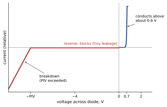
Semiconductors such as silicon conduct poorly in pure form but can be doped with impurities to create n-type material (with extra electrons) and p-type material (with "holes", missing electrons). A junction between p-type and n-type material forms a diode, which conducts easily in one direction (forward bias, anode positive) and blocks current in the other (reverse bias). A forward-biased silicon diode drops about 0.6 to 0.7 V; a Schottky diode about 0.2 to 0.4 V; an LED about 1.8 to 3.3 V depending on colour. In reverse, a diode blocks until its peak inverse voltage (PIV) rating is exceeded, when it breaks down and usually fails short.
- Rectifier diodes convert AC to DC in power supplies and drives.
- Zener diodes are designed to break down at a specific reverse voltage and are used for voltage references and simple regulation.
- Light-emitting diodes (LEDs) emit light when forward biased.
- Transient voltage suppression (TVS) diodes clamp voltage spikes.
- Freewheeling (flyback) diodes across DC coils absorb the inductive spike when the coil is switched off.
Rectifiers
Rectifiers convert AC to DC:
- A half-wave rectifier uses one diode and passes only one half of each cycle; simple but inefficient with large ripple.
- A full-wave bridge rectifier uses four diodes to pass both halves, producing pulsating DC at twice the line frequency (120 Hz from 60 Hz).
- A three-phase six-pulse bridge, with six diodes, is used at the input of most variable frequency drives and large DC supplies. It produces a DC voltage of about 1.35 times the line-to-line RMS voltage (about 810 V DC on a 600 V system or 650 V DC on 480 V) with ripple at six times line frequency, and draws characteristic 5th and 7th harmonic currents from the supply.
The average DC output of a single-phase bridge without a filter is about 0.9 times the RMS input voltage; with a capacitor filter and light load, the DC rises toward the peak, √2 times the RMS voltage (about 170 V from 120 V AC).
Worked problem
DC bus voltage of a drive
A drive is supplied at 600 V three-phase. Estimate its DC bus voltage, and explain why a technician measuring 0 V AC between the bus terminals and ground might still be at risk.
Show solution
- DC bus ≈ 1.35 × 600 = 810 V DC (approaching 1.414 × 600 ≈ 849 V at light load).
- The bus is DC, so a meter set to AC volts may read near zero even when the bus is fully charged.
- Measure with the meter on DC volts, across the bus terminals (DC+ to DC−), after waiting the time stated on the drive label.
- Verify the meter on a known source before and after the measurement.
Answer: About 810 V DC. Always measure DC across the bus with the meter on DC, after the waiting time, before touching internal parts.
Filtering and regulation
Rectified DC pulsates and must be smoothed. A filter capacitor charges near each peak and supplies current between peaks, leaving a ripple voltage that decreases with larger capacitance and lighter load. For a full-wave rectifier, ripple is approximately V_ripple = I / (2 f C). Linear voltage regulators then hold the output constant by dissipating excess voltage as heat, simple and quiet but inefficient when the voltage drop is large. Most modern power supplies are switch-mode (Lesson 3), which are far more efficient.
Optoisolators and isolation
An optoisolator (optocoupler) contains an LED and a light-sensitive transistor in one package, separated by an insulating gap. Current through the LED switches the transistor on, transferring a signal across an insulation barrier that can withstand thousands of volts. PLC input modules, drive control terminals and solid-state relays use optoisolators to protect sensitive logic circuits from field wiring noise, ground differences and surges. Understanding isolation explains why a PLC input has separate common terminals and why grounding schemes for control circuits matter (Lesson 6).
Testing electronic components safely
Electronic equipment requires care during testing:
- Use a meter rated for the measurement category (CAT III or CAT IV for distribution equipment) and voltage, and verify it before and after use.
- De-energize, lock out and discharge stored energy before measuring resistance or continuity; capacitors in drives and power supplies can hold lethal voltages for minutes.
- Use the diode test function to check diodes and semiconductor junctions: a good silicon diode reads about 0.5 to 0.7 V forward and open in reverse; a shorted diode reads near zero both ways; an open diode reads open both ways.
- Do not use an insulation resistance tester (megger) on circuits containing electronics unless they are disconnected; high test voltages destroy semiconductors. Disconnect or bypass drives, PLCs, surge protectors and electronic ballasts before insulation testing.
- Protect against electrostatic discharge (ESD) when handling circuit boards: use wrist straps and anti-static bags, and hold boards by their edges.
| Component | Common failure | How to check |
|---|---|---|
| Resistor | Opens or drifts, often after overheating | Ohmmeter with circuit de-energized; look for discoloration |
| Electrolytic capacitor | Dries out, bulges, high ESR, short | Visual inspection, ESR or capacitance meter |
| Diode | Shorts or opens | Diode test in both directions |
| LED | Opens or dims | Diode test (may glow faintly), check series resistor |
| Fuse | Opens | Continuity with power off; voltage across it when energized |
Reading electronic schematics and data sheets
Electricians increasingly need to read electronic schematics and data sheets. Schematics use standard symbols for resistors, capacitors, diodes, transistors and integrated circuits, with reference designators (R12, C3, D5, Q2, U7) that match markings on the circuit board. Power flows are usually drawn from top to bottom and signals from left to right. Ground and supply symbols indicate connections that are not drawn as wires. Data sheets list absolute maximum ratings, which must never be exceeded even momentarily, and recommended operating conditions, which give reliable long-term service, along with electrical characteristics, typical application circuits and pinouts.
When replacing a component, match not only the main value (resistance, capacitance or current rating) but also the voltage rating, power rating, temperature rating, package and, for capacitors, the ripple current and ESR. A replacement electrolytic capacitor with the right capacitance but a lower voltage or ripple rating may fail quickly. For equipment under warranty or certified for safety, component-level repair may not be permitted; replace the module or return it to the manufacturer.
Finally, many electronic failures are caused by conditions around the equipment rather than by the parts themselves: heat, dust, moisture, vibration, voltage surges and poor connections. Fixing the root cause, such as a blocked filter or a missing surge protector, prevents the replacement from failing in the same way.
As you progress through the course, you will see these basic components inside every device studied: power supplies, sensors, PLC modules and drives. Recognizing them and understanding their roles makes the more complex systems far less mysterious.
Common mistakes
MistakeMeasuring a drive DC bus on the AC voltage setting.
InsteadUse DC volts across DC+ and DC− after the discharge wait.
MistakeRunning resistors near their power rating.
InsteadKeep dissipation below about half the rating.
MistakeMegger testing circuits with connected electronics.
InsteadDisconnect electronics before insulation testing.
MistakeOmitting suppression on DC coils.
InsteadFit flyback diodes or other suppressors.
MistakeHandling circuit boards without ESD protection.
InsteadUse wrist straps and anti-static packaging.
Summary and key terms
- Resistors limit current, divide voltage and must be rated for power; LEDs need series resistors.
- Capacitors filter, store energy and set timing; electrolytics are common wear-out parts and store dangerous charge.
- Inductors oppose current change; switching them off causes spikes that need suppression.
- Diodes conduct forward (about 0.6 to 0.7 V drop) and block reverse until breakdown.
- Bridge and six-pulse rectifiers convert AC to DC; a drive bus is about 1.35 times line voltage.
- Filters and regulators smooth DC; optoisolators transfer signals across insulation barriers.
- Test safely: correct meter settings, discharge, diode tests, no megger on electronics, ESD protection.
- Voltage divider
- Two resistors producing a fraction of a voltage.
- Time constant
- The product RC governing charging time.
- Electrolytic capacitor
- A polarized, high-value capacitor.
- ESR
- Equivalent series resistance of a capacitor.
- Semiconductor
- A material whose conductivity is controlled by doping.
- Forward bias
- Voltage polarity that makes a diode conduct.
- Peak inverse voltage
- The maximum reverse voltage a diode can block.
- Bridge rectifier
- Four diodes producing full-wave DC.
- Ripple
- Residual AC variation on rectified DC.
- Optoisolator
- A device transferring signals by light across an insulation gap.
Practice problems
Work each problem on paper first, then reveal the answer to check.
Size a resistor for a 12 V supply and a 2 V LED at 15 mA.
Show answer
(12 − 2) ÷ 0.015 ≈ 667 Ω; use 680 Ω.
What is the output of a divider with Vin = 24 V, R1 = 10 kΩ, R2 = 2.2 kΩ?
Show answer
24 × 2.2 ÷ 12.2 ≈ 4.33 V.
What is the time constant of 100 kΩ and 10 µF?
Show answer
1 s.
Name two signs of a failed electrolytic capacitor.
Show answer
Bulging, leaking, high ESR.
What is the forward drop of a silicon diode?
Show answer
About 0.6 to 0.7 V.
What does a flyback diode do?
Show answer
Absorbs the voltage spike when a DC coil is switched off.
Estimate the DC bus of a drive on 208 V.
Show answer
About 1.35 × 208 ≈ 281 V DC.
Why must electronics be disconnected before megger testing?
Show answer
High test voltages destroy semiconductors.
How does a shorted diode read on diode test?
Show answer
Near zero in both directions.
What does an optoisolator provide?
Show answer
Signal transfer with electrical isolation.
Lesson quiz · 5 questions
Score 60% or more to complete this lesson.
Create a free account to save your progress, take quizzes and earn a certificate.