
ELEC-130 · Lesson 5 of 12 · 33 min
Branch circuits and receptacles
Branch circuits are the final circuits from the panel to the lights, receptacles and appliances of the house. They are where most of an electrician's residential work happens, and where the code is most detailed, because they are what occupants touch every day. This lesson covers the kinds of branch circuit and their ratings, cable and wire sizes, the number and placement of receptacles, dedicated circuits for appliances, lighting outlets and switching, and receptacle types.
Kinds of branch circuit
Residential branch circuits fall into a few groups:
- General-purpose 120 V circuits, rated 15 A (14 AWG copper) or 20 A (12 AWG copper), supplying lighting and general receptacles.
- Small-appliance and kitchen counter circuits, which carry the heavy, intermittent loads of kettles, toasters and microwaves.
- Dedicated (individual) circuits supplying one appliance: refrigerator, dishwasher, washing machine, microwave, furnace, sump pump and so on.
- 240 V circuits for large appliances: range (commonly 40 A), dryer (30 A), water heater, baseboard heaters, heat pumps and air conditioners, EV chargers.
- Multiwire branch circuits: two ungrounded conductors from opposite buses sharing one neutral, for example to supply a split kitchen receptacle. The neutral carries only the difference of the two currents, saving a conductor, but the two hots must be on a two-pole breaker or handle-tied breakers so both are disconnected together.
The circuit rating is set by the overcurrent device, and the conductors must be protected by it. The small-conductor rule from ELEC-120 applies: 14 AWG copper on no more than 15 A, 12 AWG on 20 A and 10 AWG on 30 A, regardless of the higher ampacity of 90 °C insulation.
| Load | Typical circuit | Copper conductor (non-metallic cable) |
|---|---|---|
| Lighting, general receptacles | 15 A, 120 V | 14 AWG |
| Kitchen counter, bathroom, laundry | 20 A, 120 V (or split 15 A) | 12 AWG (14 AWG for 15 A) |
| Dryer | 30 A, 240 V | 10 AWG |
| Range | 40 A, 240 V | 8 AWG |
| EV charger (7.7 kW at 32 A continuous) | 40 A, 240 V | 8 AWG |
| Baseboard heaters 3 kW | 15 A or 20 A, 240 V | 14 or 12 AWG |
Worked problem
Sizing an EV charger circuit
An EV charger draws 32 A continuously at 240 V. What breaker and copper conductor are needed?
Show solution
- Continuous load: the overcurrent device must be at least 125% of the load: \(1.25 \times 32 = 40\) A.
- A 40 A breaker with conductors rated at least 40 A at the termination temperature: 8 AWG copper (non-metallic cable is limited to the 60 °C column, where 8 AWG is rated 40 A).
Answer: A 40 A two-pole breaker and 8 AWG copper. The charger counts at its full rating in the load calculation (Lesson 1), and in both countries it must be on its own circuit.
Cable and wiring practice
Most Canadian houses are wired with non-metallic sheathed cable, NMD90, which has two or three insulated copper conductors and a bare bonding conductor in a PVC jacket; armoured cable (AC90) is used where the cable may be exposed to damage. NMD90 must be supported within 300 mm of each box and at intervals of not more than 1.5 m, and protected where it passes through framing near the face of a stud or joist.
Wiring is planned so that circuits are logical and well labelled: lights and receptacles of a room are often on different circuits, so a tripped breaker does not leave a room dark; high-load receptacles are spread across circuits; and 120 V circuits are balanced between the two buses (Lesson 3). The panel directory must identify every circuit clearly.
Receptacle spacing
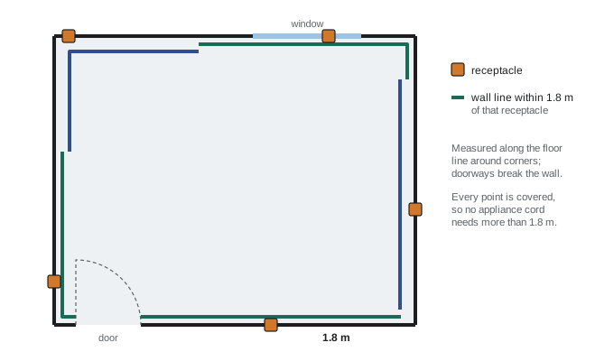
Receptacles must be placed so that a lamp or appliance with a normal cord can reach one from anywhere along a wall, which discourages extension cords.
The Canadian Electrical Code requires receptacles in finished rooms of a dwelling to be located so that no point along the floor line of any usable wall space is more than 1.8 m horizontally from a receptacle, measured along the wall. Wall spaces 900 mm or more wide count as usable, and doorways, fireplaces and similar openings break the wall. Hallways, bathrooms, kitchens and laundry areas have their own rules.
Worked problem
Receptacles for a room
A bedroom wall has a continuous usable length of 7.5 m from the door frame to the corner. What is the minimum number of receptacles along it?
Show solution
- Each receptacle covers 1.8 m on each side, a 3.6 m stretch.
- The first can be at most 1.8 m from the door; then every 3.6 m: positions at 1.8 m and 5.4 m cover 0 to 7.2 m; 7.2 to 7.5 m is not covered, so a third is needed (or move the second to cover to the corner: 1.8 m and 5.7 m cover 0–3.6 and 3.9–7.5, leaving 3.6–3.9 m uncovered).
Answer: Three receptacles. A useful rule is n = ⌈L / 3.6 m⌉, counting from the openings, with corners continuing around onto the next wall.
Kitchens
Kitchens have the most demanding requirements, because counters host many high-current appliances.
In Canada, counter work surfaces must have receptacles so that no point along the wall line of the counter is more than 900 mm from a receptacle, with at least one receptacle for each counter section 300 mm or more wide, and receptacles for islands and peninsulas. Counter receptacles are supplied either by 20 A circuits with 5-20R (T-slot) receptacles, or by 15 A split receptacles on multiwire circuits, and the code limits how many counter receptacles may share a circuit. A separate receptacle is required for the refrigerator, and dedicated circuits are typical for the dishwasher, microwave and range.
Worked problem
Counter receptacles
An L-shaped counter has wall lengths of 3.0 m and 2.2 m, with a sink in the corner that is not on a wall space break. How many receptacles are needed along the counter wall line, at minimum?
Show solution
- Each receptacle covers 900 mm on each side, 1.8 m in all. Total wall line: 5.2 m.
- \(5.2/1.8 = 2.9\), so at least 3 receptacles, placed at about 0.9 m, 2.7 m and 4.5 m along the wall line.
Answer: Three receptacles, each a 20 A T-slot or a split 15 A receptacle, with no more than the permitted number per circuit.
Bathrooms, laundry, outdoors and garages
- Bathrooms: at least one receptacle within 1 m of the washbasin, protected by a GFCI; receptacles must not be within a set distance of the bathtub or shower.
- Laundry: a receptacle for the washing machine, normally on its own circuit, plus a dryer circuit.
- Outdoors: at least one receptacle for a single dwelling, accessible from the ground, GFCI protected, with an in-use (bubble) cover where exposed to rain.
- Garages and carports: at least one receptacle for each car space (traditionally for block heaters), and some provinces and municipalities now require new houses to be ready for EV charging, with a circuit or conduit in place.
Number of outlets per circuit
The Canadian Electrical Code limits a 15 A general-purpose branch circuit to no more than 12 outlets (each receptacle or lighting outlet counts as one), which keeps circuits from being overloaded by many small loads. Kitchen counter circuits have their own, tighter limit.
Worked problem
Planning general-purpose circuits
A basement renovation adds 28 receptacles and 9 lighting outlets on 15 A general-purpose circuits. What is the minimum number of circuits?
Show solution
- Total outlets: \(28 + 9 = 37\).
- At 12 per circuit: \(37/12 = 3.1\), so 4 circuits.
Answer: At least 4 circuits, though 5 or 6 would separate lighting from receptacles and keep loads modest.
Lighting outlets and switching
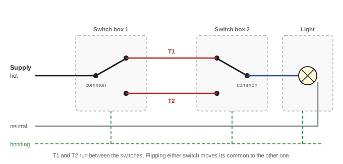
Every habitable room, bathroom, hallway, stairway, attached garage and outdoor entrance needs a lighting outlet controlled by a wall switch near the entrance (in living rooms, a switched receptacle may be accepted in place of a ceiling outlet). Stairways with six or more risers, and rooms with more than one entrance, commonly need switches at each end or entrance:
- A single-pole switch controls a light from one place.
- Two three-way switches control a light from two places: the supply goes to the common terminal of the first switch, two travellers connect the switches, and the common of the second switch feeds the light.
- Four-way switches inserted between the two three-ways add each further control location.
Smart switches, occupancy sensors and dimmers usually need a neutral at the switch box. Bringing a neutral to every switch location is therefore good practice even where the code does not demand it, because adding one later means fishing new cable. Dimmers must be compatible with the lamps, especially LED lamps, and rated for the load.
Worked problem
Voltage drop on a long branch circuit
A 15 A, 120 V circuit of 14 AWG copper (8.28 Ω/km, or 2.53 Ω/1000 ft) runs 30 m (98 ft) to a garage receptacle that will supply a 12 A tool. What is the voltage drop? Is 12 AWG (5.21 Ω/km) better?
Show solution
- 14 AWG: the circuit loop is 60 m, \(R = 0.060 \times 8.28 = 0.497\) Ω; drop \(= 12 \times 0.497 = 5.96\) V, or 5.0%.
- 12 AWG: \(R = 0.060 \times 5.21 = 0.313\) Ω; drop \(= 3.75\) V, or 3.1%.
Answer: About 6 V (5%) with 14 AWG, above the usual 3% branch-circuit target, and 3.75 V (3.1%) with 12 AWG on a 15 A or 20 A breaker. Long runs to garages and outbuildings are routinely upsized for voltage drop.
Receptacle types
Receptacle configurations are standardized by NEMA (and in Canada by CSA, which uses the same configurations) so that a plug fits only a matching voltage and current rating:
- 5-15R: 15 A, 125 V, the ordinary duplex receptacle. 5-20R: 20 A, 125 V, with a T-shaped slot that accepts both 15 A and 20 A plugs.
- 14-30R: 30 A, 125/250 V, four-wire, for dryers. 14-50R: 50 A, 125/250 V, four-wire, for ranges and plug-in EV chargers.
- 6-20R, 6-30R and 6-50R: 250 V receptacles without neutral.
Older three-wire 10-30 and 10-50 receptacles, which use the neutral as the equipment ground, are no longer permitted for new installations; new dryer and range circuits use four-wire receptacles with a separate equipment grounding conductor.
Receptacles in dwellings must be tamper-resistant, with internal shutters that keep children from inserting objects into one slot. Outdoor receptacles and those in wet locations need weatherproof or in-use covers.
Lesson 6 continues with the circuits for ranges, dryers, water heaters, pumps and other major appliances, and Lesson 4 covers how the cable and boxes for these circuits are installed.
Common mistakes
MistakePutting 14 AWG on a 20 A breaker because 90 °C insulation is rated higher.
InsteadThe small-conductor rule limits 14 AWG copper to 15 A and 12 AWG to 20 A.
MistakeWiring a multiwire circuit with two single-pole breakers.
InsteadUse a two-pole breaker or identified handle tie so both hots disconnect together, and land the hots on opposite buses.
MistakeMeasuring receptacle spacing as a straight line across the room.
InsteadMeasure along the floor line of the wall, with doorways and openings breaking the wall.
MistakeSizing a continuous load like an EV charger at its running current.
InsteadSize the breaker at 125% of continuous load and the conductors to match.
MistakeInstalling three-wire dryer or range receptacles in new work.
InsteadNew dryer and range circuits use four-wire receptacles with a separate equipment grounding conductor.
MistakeOmitting the neutral at switch boxes.
InsteadBring a neutral to switch locations so smart switches and sensors can be fitted later.
Summary and key terms
- Branch circuits: general-purpose 15/20 A, small-appliance and counter, dedicated appliance, 240 V appliance, and multiwire circuits.
- Small-conductor rule: 14 AWG on 15 A, 12 AWG on 20 A, 10 AWG on 30 A; continuous loads at 125%.
- NMD90 cable: support within 300 mm of boxes and every 1.5 m.
- Receptacle spacing: no point along a usable wall more than 1.8 m from a receptacle.
- Kitchen counters: no point more than 900 mm from a receptacle; 20 A T-slot or split 15 A receptacles, limited per circuit; separate refrigerator receptacle.
- Bathroom receptacle within 1 m of the basin; at least one outdoor receptacle; maximum 12 outlets per 15 A circuit.
- Lighting outlets with wall switches in every room; three-way and four-way switches for multiple locations; neutrals at switch boxes.
- Receptacle configurations: 5-15, 5-20, 14-30, 14-50; tamper-resistant in dwellings; weather-resistant with in-use covers outdoors.
- Branch circuit
- The circuit conductors between the final overcurrent device and the outlets.
- General-purpose circuit
- A branch circuit supplying lighting and general receptacles.
- Dedicated circuit
- A branch circuit supplying a single appliance or outlet.
- Multiwire branch circuit
- Two or more ungrounded conductors sharing a neutral.
- Small-appliance circuit
- A 20 A circuit for kitchen and dining receptacles.
- Split receptacle
- A duplex receptacle whose two halves are fed from different circuits.
- Outlet
- A point on the wiring where current is taken to supply equipment.
- Three-way switch
- A switch with a common and two traveller terminals, used in pairs.
- Traveller
- A conductor between three-way or four-way switches.
- Tamper-resistant receptacle
- A receptacle with shutters that block single-slot insertion.
- In-use cover
- A weatherproof cover that protects a receptacle while a plug is inserted.
- Voltage drop
- The reduction in voltage along conductors due to their resistance.
Practice problems
Work each problem on paper first, then reveal the answer to check.
What breaker and copper conductor size suit a 24 A continuous load at 240 V?
Show answer
1.25 × 24 = 30 A breaker; 10 AWG copper.
A multiwire circuit carries 12 A on one hot and 9 A on the other. What is the neutral current?
Show answer
3 A, if the hots are on opposite buses.
What happens to the neutral of a multiwire circuit if both hots are mistakenly on the same bus?
Show answer
The currents add instead of cancelling: 21 A on a conductor rated for 15 or 20 A, overheating the neutral without tripping either breaker.
A wall runs 4.0 m between two doorways. How many receptacles at minimum?
Show answer
One receptacle covers 3.6 m; 4.0 m needs 2 (one alone placed at 2.0 m leaves 0.2 m at each end uncovered).
How many 15 A general-purpose circuits are needed for 50 outlets?
Show answer
50/12 = 4.2, so 5.
What is the voltage drop on a 25 m run of 12 AWG copper (5.21 Ω/km) carrying 16 A at 120 V?
Show answer
R = 0.050 × 5.21 = 0.26 Ω; 16 × 0.26 = 4.2 V, 3.5%.
Describe how two three-way switches control one light.
Show answer
The supply goes to one switch's common, two travellers join the switches, and the other common feeds the light; the light is on when both switches select the same traveller.
Which receptacle configuration suits a new electric dryer circuit?
Show answer
NEMA 14-30R (30 A, 125/250 V, four-wire with separate ground).
Why must new range and dryer circuits be four-wire?
Show answer
So that the equipment frame is bonded through a separate grounding conductor rather than the neutral, which carries current and could energize the frame if it opened.
Why are lights and receptacles of a room often put on different circuits?
Show answer
So a tripped receptacle circuit does not leave the room dark, and to spread load.
Lesson quiz · 5 questions
Score 60% or more to complete this lesson.
Create a free account to save your progress, take quizzes and earn a certificate.