
ELEC-130 · Lesson 9 of 12 · 31 min
Inspection and testing
A residential installation is not finished when the last device is screwed in. It must be inspected by the authority that issued the permit, and it should be tested by the electrician before anyone else sees it, so that mistakes are found while walls are still open and before a family moves in. Testing also continues through a house's life: troubleshooting a tripping breaker, checking an old house before renovations or verifying that a repair is safe. This lesson covers permits and the inspection sequence, what inspectors look for, the standard tests and the instruments used for them, working safely while testing, and documentation.
Permits and the inspection sequence
In Canada, electrical permits and inspections are the responsibility of the provincial or territorial electrical safety authority, which in some provinces delegates them to municipalities or accredited agencies; examples include the Electrical Safety Authority in Ontario, Technical Safety BC, and the Régie du bâtiment and Corporation des maîtres électriciens in Quebec. A licensed electrical contractor normally obtains the permit before starting, although several provinces allow homeowners to obtain a permit for work on their own dwelling. The utility will not connect a new or upgraded service until the inspection authority has authorized it.
Inspections follow the stages of construction:
- Rough-in (cover) inspection: after boxes are mounted, cables pulled and secured, bonding connections made and fire separations sealed, but before insulation and drywall cover the wiring. This is the most important inspection, because afterwards the wiring is hidden.
- Service inspection: of the meter base, service conductors, panel, grounding electrodes and bonding, so that the utility can connect permanent power. On new houses it may occur with or before the rough-in.
- Final inspection: after devices, fixtures, covers and appliances are installed, panels labelled and the system energized and tested.
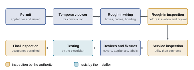
What inspectors check at rough-in
An inspector works through the installation methodically. Typical items include:
- Cable type suitable for the location, secured near each box and at regular intervals, not stapled too tightly, and protected where it passes close to framing edges or through metal studs.
- Boxes securely fastened, set flush with the finished wall surface, of adequate volume for the conductors and devices (box fill, ELEC-120), with cable clamps or connectors.
- Bonding conductors connected to every metal box and to each other, and enough conductor length left in boxes for connections.
- Required receptacle, lighting and switch locations; dedicated circuits; correct conductor sizes for each breaker.
- Sealing of penetrations through fire separations (for example between an attached garage and the house) with approved methods.
- Panel installation: working space, breaker types, labelling, neutrals and bonding.
Testing before energizing
Continuity and bonding
A low-resistance ohmmeter or continuity tester checks that every metal box, receptacle grounding terminal and appliance frame is connected to the bonding system, and that conductors are continuous from the panel to each outlet. A reading of a fraction of an ohm between a receptacle's grounding terminal and the panel's ground bar (allowing for test lead resistance) confirms the bonding path.
Insulation resistance
An insulation resistance tester (often called a megger, after a brand) applies a DC test voltage, typically 500 V for 120/240 V wiring, between conductors and between each conductor and ground, and measures the very small leakage current to give a resistance in megohms. New residential wiring normally reads hundreds of megohms or more; a low reading reveals a nail or staple through a cable, damaged insulation, water in a box, or a conductor pinched against a box. Values below about 1 MΩ indicate a fault that must be found. Before testing, disconnect or open circuits to electronic devices, such as dimmers, smart switches, GFCI and AFCI devices and appliances, which the test voltage could damage or which would give false low readings.
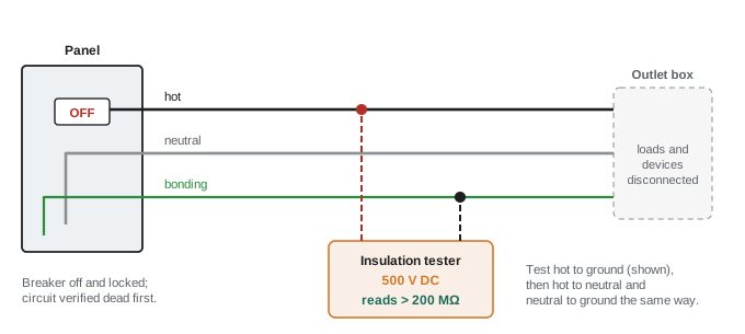
Worked problem
Insulation resistance of circuits in parallel
Three branch circuits are tested together from the panel, with their neutrals and hots joined, against ground. Individually they would read 400 MΩ, 300 MΩ and 2 MΩ. What does the combined test read, and what should the electrician conclude?
Show solution
- Insulation resistances in parallel combine like resistors: \(1/R = 1/400 + 1/300 + 1/2 = 0.0025 + 0.0033 + 0.5 = 0.506\).
- \(R = 1/0.506 = 1.98\) MΩ.
Answer: About 2 MΩ, dominated entirely by the third circuit. A combined reading near the 1 MΩ threshold means testing circuits one at a time to find the poor one; here, the 2 MΩ circuit probably has a damaged cable or moisture and should be investigated even though it is above 1 MΩ, because new wiring should read far higher.
Polarity and the receptacle tester
After energizing, each receptacle is checked for correct wiring: the hot on the narrow (brass) slot, the neutral on the wide (silver) slot and the grounding terminal bonded. Plug-in testers with three lamps quickly show common faults such as open ground, open neutral, reversed polarity or hot on ground. They have important limits: they cannot detect a "bootleg" ground (a jumper from neutral to ground terminal at the receptacle, which makes a missing ground look correct but puts the frame of plugged-in equipment at the neutral's voltage), a reversed hot and ground in some combinations, or high-resistance connections. A voltmeter between each pair of contacts, and a check of the bonding path back to the panel, are more conclusive.
| Measurement | Correct reading (120 V circuit) | What a wrong reading suggests |
|---|---|---|
| Hot to neutral | About 120 V | 0 V: open hot or neutral |
| Hot to ground | About 120 V | 0 V: open ground or reversed hot and ground |
| Neutral to ground | Near 0 V (a volt or two under load) | About 120 V: reversed polarity; several volts: long or overloaded neutral, or loose neutral connection |
Ground-fault and arc-fault devices
Every GFCI is tested with its own TEST button (which must trip it) and preferably with an external GFCI tester that draws a measured leakage current through the grounding conductor, confirming that downstream receptacles are protected and that the device trips at the correct level. AFCI breakers are tested with their TEST button; plug-in AFCI testers only simulate an arc signature and are not a definitive test of the breaker's arc detection.
Fault current and voltage drop
For a breaker to protect against a short circuit it must trip quickly, which requires the fault current to reach its instantaneous (magnetic) trip level, commonly 5 to 10 times its rating for residential breakers. The fault current at the end of a long branch circuit depends on the loop impedance: the source impedance plus the resistance out and back along the circuit. Loop impedance testers, common in Europe, measure it directly; in North America the check is usually done by calculation or with a voltage-drop tester that applies a known load.
Worked problem
Will the breaker trip quickly?
A 15 A circuit of 14 AWG copper (8.28 Ω/km) runs 30 m to the last receptacle. The source impedance at the panel is 0.05 Ω. If the hot and bonding conductor are short-circuited at the receptacle (the bonding conductor is also 14 AWG), what fault current flows? Does it exceed 10 times the breaker rating?
Show solution
- Loop resistance: out and back, \(2 \times 30\) m \(= 60\) m: \(0.060 \times 8.28 = 0.497\) Ω.
- Total with source: \(0.497 + 0.05 = 0.547\) Ω.
- Fault current: \(120/0.547 = 219\) A, compared with \(10 \times 15 = 150\) A.
Answer: About 220 A, so the breaker trips magnetically within a cycle or two. On very long circuits (over about 45 m of 14 AWG), the fault current approaches the magnetic trip level and clearing time lengthens, another reason to upsize long runs. Arc resistance in a real fault lowers the current further.
Grounding electrode resistance
The resistance of a grounding electrode to earth can be measured with the fall-of-potential method, which uses two auxiliary test stakes driven in line with the electrode, or with a clamp-on earth tester on suitable systems. The Canadian Electrical Code relies primarily on prescribed electrodes (such as two rods at least 3 m apart) rather than a measured resistance value for dwellings, but measurements are useful for troubleshooting and for special installations.
Working safely while testing
Testing exposes the electrician to live parts. The essential practices are:
- Treat every conductor as live until proven otherwise. Isolate circuits by switching off and locking out the breaker (lockout and tagout) when work does not need to be done live.
- Verify absence of voltage with the live-dead-live method: test the voltage tester on a known live source, test the circuit, then test the known source again, which proves the tester did not fail during the test.
- Use test instruments with the right measurement category rating for where they are used: CAT III for panelboards and branch circuits in buildings, CAT IV at the service entrance and meter base, and probes with guarded tips.
- Wear appropriate personal protective equipment, including arc-rated clothing and face protection where the task requires it, and never work alone on energized equipment.
In Canada, CSA Z462, Workplace Electrical Safety, sets the requirements for an electrical safety program, energized work, approach boundaries and PPE, and provincial occupational health and safety regulations make lockout and safe work practices mandatory.
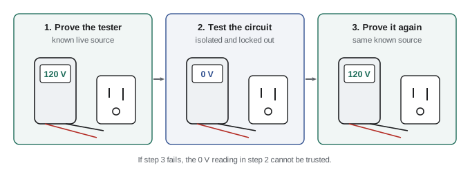
Troubleshooting common problems
Inspection and testing skills are used daily in service work. Some typical cases:
- A breaker trips immediately: a short circuit or ground fault. Disconnect loads and test insulation resistance by section to locate it.
- A breaker trips after running for a while: an overload (sum the loads on the circuit) or a heating connection.
- Lights dim or brighten when large loads start: a loose service or branch neutral, or excessive voltage drop. Measure neutral-to-ground voltage under load and check connections; an open service neutral is an emergency (Lesson 3).
- Warm switch plates or receptacles, discolouration or a burning smell: loose terminals or overloaded devices. Infrared thermography can find hot connections under load without opening covers.
- Backstabbed receptacles (conductors pushed into spring terminals on the back) are a frequent cause of failed connections in older houses; using the screw terminals or back-wire clamps is more reliable.
Worked problem
Diagnosing a bootleg ground
In an older house, a three-lamp tester shows "correct" at a bedroom receptacle fed by a two-wire cable that has no bonding conductor. With all other loads off, the electrician measures 0.0 V from neutral to ground. A 1500 W heater on the same circuit is then switched on: hot to neutral drops from 121 V to 118 V, but neutral to ground still reads 0.0 V. What is happening?
Show solution
- In correct wiring, the grounding terminal returns to the panel on its own conductor, which carries no current. Under load the neutral drops a few volts along its length, so neutral to ground rises (here it should be about 3 V, matching the 121 V to 118 V drop).
- A reading that stays at 0.0 V under load means the neutral and ground terminals are joined at or near the receptacle, so they cannot differ.
- Combined with a cable that has no bonding conductor, this points to a jumper from the neutral terminal to the ground screw; removing the cover plate confirms it.
Answer: A bootleg ground. Any plugged-in metal-cased appliance has its frame connected to the current-carrying neutral, which becomes live if the neutral opens upstream. The fix is to remove the jumper and either install a bonding conductor, or protect the circuit with a GFCI and label the receptacles "No Equipment Ground" and "GFCI Protected".
Documentation and handover
A good installation ends with records that the next electrician and the owner can rely on:
- A legible, specific panel directory: "Kitchen counter left of sink", not "Plugs".
- Labels on the service equipment as required by the code, such as the main disconnect, and any generator or solar interconnection warnings.
- Test records: insulation resistance values, GFCI and AFCI tests, and any measured grounding electrode resistance, kept by the contractor.
- Manufacturer instructions for installed equipment (EV charger, heat pump, smoke alarms) left with the owner, along with the permit and inspection certificates.
Lesson 11 extends troubleshooting to older houses with legacy wiring, and Lesson 12 applies the full inspection and testing sequence to a complete house project.
Common mistakes
MistakeCovering wiring with insulation or drywall before the rough-in inspection.
InsteadCall for the rough-in inspection while everything is visible; covering it can mean removing finishes.
MistakeRunning a 500 V insulation test with dimmers, smart devices or GFCIs connected.
InsteadDisconnect electronics and appliances first; the test voltage can damage them and they give false readings.
MistakeRelying on a three-lamp tester to prove a receptacle is safe.
InsteadIt cannot detect bootleg grounds or high-resistance connections; use a voltmeter and check the bonding path.
MistakeTesting a circuit dead with a tester that has not been proven.
InsteadUse live-dead-live, and a CAT-rated instrument suitable for the location.
MistakeWriting vague panel directories.
InsteadIdentify each circuit specifically so anyone can isolate it quickly.
Summary and key terms
- Permits and inspections come from the provincial or territorial electrical safety authority; utilities connect only after authorization.
- Inspections: rough-in (before cover), service, and final.
- Rough-in checks: cable type, support and protection, box mounting and fill, bonding, outlet locations, fire separations and the panel.
- Continuity tests confirm bonding; insulation resistance at 500 V DC should read hundreds of MΩ (below about 1 MΩ indicates a fault); disconnect electronics first.
- Check polarity with a voltmeter; plug-in testers miss bootleg grounds.
- Test GFCIs and AFCIs at installation; GFCI testers confirm trip level and downstream protection.
- Fault current must reach the breaker's magnetic trip level; long, small circuits reduce it.
- Safe testing: lockout, live-dead-live, CAT III/IV meters, PPE per CSA Z462.
- Document with clear panel directories, labels and test records.
- Permit
- Authorization from the inspection authority to perform electrical work.
- Rough-in inspection
- Inspection of wiring before it is concealed by insulation and finishes.
- Final inspection
- Inspection of the completed installation.
- Insulation resistance test
- A DC high-voltage test measuring leakage resistance between conductors and to ground.
- Continuity test
- A test confirming a conductor or bonding path is unbroken.
- Polarity
- The correct connection of hot and neutral to their intended terminals.
- Bootleg ground
- An illegal jumper from neutral to the ground terminal at a receptacle.
- Loop impedance
- The total impedance of the fault path from source to fault and back.
- Fall-of-potential test
- A method of measuring grounding electrode resistance using auxiliary stakes.
- Live-dead-live
- Verifying a voltage tester on a known source before and after testing a circuit.
- Measurement category
- The CAT rating of a test instrument for the transient levels at its location.
- Lockout and tagout
- Procedures that keep isolated equipment from being re-energized during work.
- Infrared thermography
- Using a thermal camera to find hot connections and overloaded equipment.
Practice problems
Work each problem on paper first, then reveal the answer to check.
Why is the rough-in inspection the most important?
Show answer
After insulation and drywall, the wiring is hidden; problems found later require removing finishes.
What test voltage is typical for insulation testing 120/240 V wiring, and what readings are expected?
Show answer
500 V DC; new wiring reads hundreds of megohms; below about 1 MΩ indicates a fault.
Two circuits tested together read 5 MΩ. One alone reads 500 MΩ. What does the other read?
Show answer
1/5 = 1/500 + 1/R gives 1/R = 0.198, R ≈ 5.05 MΩ: the second circuit is the poor one.
A receptacle reads 120 V hot to neutral, 0 V hot to ground and 120 V neutral to ground. What is wrong?
Show answer
Hot and ground are reversed (the ground terminal is energized): dangerous; de-energize and correct.
Name two faults a three-lamp tester cannot detect.
Show answer
A bootleg ground; a high-resistance connection; some hot/ground reversals.
A 20 A circuit of 12 AWG (5.21 Ω/km) runs 40 m. With 0.05 Ω source impedance, what is the bolted fault current at the end?
Show answer
Loop 0.080 × 5.21 = 0.417 Ω; total 0.467 Ω; 120/0.467 = 257 A, above 10 × 20 = 200 A.
Describe live-dead-live.
Show answer
Test the tester on a known live source, test the circuit for absence of voltage, then test the known live source again.
What measurement category should a meter have for work at the meter base?
Show answer
CAT IV (origin of the installation).
A homeowner reports lights brighten when the dryer runs and dim when the microwave starts. What do you suspect and check first?
Show answer
A loose or open service neutral: measure L1–N and L2–N under changing loads and inspect the neutral connections at the meter base and panel; treat as urgent.
Rewrite the panel directory entry "Plugs" for a circuit serving the bedroom receptacles on the north wall of the master bedroom.
Show answer
For example: "Primary bedroom, north wall receptacles" (and note any other outlets on the circuit).
Lesson quiz · 5 questions
Score 60% or more to complete this lesson.
Create a free account to save your progress, take quizzes and earn a certificate.