
ELEC-130 · Lesson 2 of 12 · 30 min
Planning a dwelling's electrical system
Lesson 1 calculated how large a house's service must be. Before any cable is pulled, the electrician (or designer) must also decide where every outlet, switch and light goes, how they are grouped into circuits, where the panel sits, and how cables will run through the structure. Good planning produces an installation that meets the code, suits the people who live in the house, is easy to inspect and maintain, and leaves room for the electric vehicles, heat pumps and solar panels that homeowners increasingly add. This lesson covers reading residential drawings, walking through a house room by room, grouping outlets into circuits, building a panel schedule, and planning for the future.
Reading residential electrical drawings
For new houses, the architect's floor plans usually include an electrical layout, or the electrician prepares one for the permit. It uses standard symbols drawn on the floor plan:
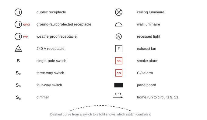
Curved dashed lines connect switches to the lights they control. A home run arrow with circuit numbers shows that the cable from that outlet returns to the panel on those circuits. Notes on the drawing specify mounting heights, special receptacles (for example a 240 V receptacle for a range or a USB receptacle), and equipment supplied by others (a furnace, a heat pump, a hot tub).
Many smaller jobs have no drawings beyond a sketch, and the electrician lays out the work with the homeowner on site, marking box locations on the studs during a walk-through. Either way, the layout is checked against the code requirements for receptacle spacing, required circuits and protection before roughing in.
A room-by-room walk-through
Planning room by room ensures nothing is missed. For each room the questions are: how will it be used, where will furniture and appliances go, which outlets does the code require, and what does the owner want beyond that?
- Entrances and hallways: a switched light at each entrance and exterior door, three-way switching at each end of halls and stairways, receptacles in longer halls, doorbell and smoke alarm locations.
- Living and bedrooms: receptacles meeting the spacing rule (Lesson 5), a switched light or switched receptacle, extra receptacles where televisions, computers and bedside lamps will sit, possibly data and coaxial outlets.
- Kitchen: counter receptacles at the required spacing on the required circuits, receptacles for the refrigerator, microwave and dishwasher, the range or cooktop and oven circuits, lighting under cabinets and over the island, a range hood (Lessons 5 and 6).
- Bathrooms: a receptacle near the basin with ground-fault protection, a light and exhaust fan, often a heated floor.
- Laundry: a receptacle for the washer, a dryer circuit, sometimes a utility sink.
- Basement and utility areas: the panel, furnace or heat pump, water heater, sump pump, lighting at stairs and in each area, receptacles for future finishing.
- Garage and exterior: receptacles with ground-fault protection, lighting at doors and the garage door opener, an EV charger or its future circuit, outdoor receptacles at the front and back, exterior lighting.
Worked problem
Counting outlets in a bedroom
A bedroom is 3.6 m by 4.2 m with a door on one 3.6 m wall and a closet occupying 1.8 m of one 4.2 m wall. In a Canadian dwelling, where no point along a usable wall may be more than 1.8 m from a receptacle, how many receptacles are needed at minimum, and where?
Show solution
- Usable walls: the 4.2 m wall opposite the closet; the 4.2 m wall minus the 1.8 m closet leaves 2.4 m; the 3.6 m wall with the door (about 2.7 m usable in pieces); the other 3.6 m wall.
- A receptacle covers 1.8 m either side along the wall, and coverage continues around corners.
- A practical layout: one receptacle on each long wall near the middle, and one near each end of the window wall, placed where beds and desks are expected: four in all, with possibly a fifth by the door section.
Answer: About four or five receptacles, positioned so every point along the walls is within 1.8 m of one, with extras where the owner wants them, for instance on both sides of the bed. The US rule is the same in principle (no point more than 6 ft from a receptacle).
Grouping outlets into circuits
Once outlets are placed, they are assigned to circuits. Good practice, beyond code minimums:
- Separate required circuits first: kitchen counter, bathroom, laundry, and individual appliance circuits (Lessons 5 and 6).
- Do not put all of a floor's lighting on one circuit: if it trips, the occupants should not be in darkness. Lights and receptacles of a room are often on different circuits.
- Limit the number of outlets per circuit so that typical loads fit comfortably: many electricians keep general circuits to about 8 to 12 outlets, and fewer where heavy plug-in loads are expected, such as home offices with computers and space heaters.
- Group outlets that are physically close, to keep cable runs short and voltage drop low.
- Spread 120 V circuits evenly across the two legs of the panel so the neutral current and the loading on each leg stay balanced (Lesson 3).
In Canada, the CEC limits the number of outlets on a 15 A branch circuit in a dwelling (Rule 8-304 sets a general maximum of 12 outlets per circuit), and requires AFCI protection for most 125 V, 15 A and 20 A receptacle circuits in dwelling units.
Worked problem
Estimating circuit load
A home office has a desktop computer (300 W), two monitors (40 W each), a laser printer (peaks 900 W while printing), lighting (60 W) and a 1,500 W space heater used in winter. Can it share a 15 A, 120 V circuit with a bedroom?
Show solution
- Office load without heater: \(300 + 80 + 900 + 60 = 1{,}340\) W at peak, 11.2 A.
- With the heater: 2,840 W, 23.7 A, more than a 15 A circuit can carry.
Answer: No. The heater alone uses 12.5 A. The office should have its own 20 A circuit (or two 15 A circuits), and the heater ideally a permanent heating circuit (Lesson 8). Planning for actual use avoids nuisance trips and overloaded extension cords.
The panel schedule
A panel schedule lists every circuit: its number, description, breaker size and poles, the conductor size, the protection type (standard, AFCI, GFCI or dual function), and the estimated load. It is used to choose the panel size (number of spaces), to balance the legs, and later as the basis of the panel directory required on the panel door.
| Circuit | Description | Breaker | Protection | Wire (Cu) |
|---|---|---|---|---|
| 1, 3 | Range | 40 A 2-pole | Standard | 8 AWG |
| 2, 4 | Dryer | 30 A 2-pole | Standard | 10 AWG |
| 5 | Kitchen counter A | 20 A | GFCI/AFCI as required | 12 AWG |
| 6 | Kitchen counter B | 20 A | GFCI/AFCI as required | 12 AWG |
| 7 | Refrigerator | 15 A | AFCI as required | 14 AWG |
| 8 | Bathroom receptacle | 20 A | GFCI | 12 AWG |
| 9 | Bedrooms 1 and 2 receptacles | 15 A | AFCI | 14 AWG |
| 10 | Upper floor lighting | 15 A | AFCI | 14 AWG |
| 11, 13 | Heat pump | 30 A 2-pole | Standard | 10 AWG |
| 12, 14 | EV charger | 40 A 2-pole | GFCI if required | 8 AWG |
Worked problem
Counting panel spaces
A house plan has 6 two-pole circuits (range, dryer, water heater, heat pump, air handler, EV charger) and 24 single-pole circuits. How many spaces are needed, and what panel would you choose, allowing for growth?
Show solution
- Two-pole circuits: \(6 \times 2 = 12\) spaces; single-pole: 24 spaces; total 36.
- Allow about 20% spare: \(36 \times 1.2 = 43\).
Answer: At least 36 spaces; a 42- or 48-space (sometimes called 40/60 or 60-circuit) panel is a sensible choice. Running out of spaces is a common reason for costly panel replacements or sub-panels later.
Routing cables through the structure
Before roughing in, the electrician plans cable routes: up from the basement or panel through the plates of interior walls, along joists, and into each box. The goals are short runs, few crossings of exterior walls and fire separations, protection from nails and screws, and access for future work.
- Interior walls are preferred for vertical runs; exterior walls are full of insulation and, in cold climates, have air and vapour barriers that must be kept continuous around boxes.
- Holes are bored near the centre of studs and joists and kept within the limits the building code sets for structural members.
- Fire separations, such as walls and ceilings between an attached garage and the house, or between dwelling units, must not be weakened; penetrations are sealed with listed firestopping.
- Space is left in ceilings and basements for future runs, and a spare conduit from the panel to the attic or to the garage is a cheap addition that saves much work later.
In Canadian cold-climate construction, boxes in exterior walls and insulated ceilings are usually vapour-barrier boxes (with a flange to which the polyethylene air and vapour barrier is sealed), so that warm, moist indoor air cannot leak into the wall cavity and condense.
Planning for the future
Houses are being electrified: gas furnaces replaced by heat pumps, gas ranges by induction, cars by electric vehicles, plus solar panels and home batteries. An installation planned today should anticipate them (Lessons 8 and 10):
- Service size: 200 A is now common for new single-family houses, and some designers specify more for all-electric homes, or plan load management instead (Lesson 10).
- Panel spaces: generous spare spaces and, where possible, two-pole spaces for future 240 V loads.
- Rough-ins: a 240 V circuit or conduit to the garage or driveway for an EV charger, to the range location even if a gas range is installed, and to the exterior where a heat pump might go; a conduit from the panel to the attic for future solar.
- Smart panels and load management devices that monitor and control circuits, allowing larger loads on a given service.
Worked problem
Is the service big enough for later?
A new house with gas heating calculates to 95 A. The owner plans, within ten years, a heat pump (20 A at 240 V), an induction range (already counted), and an EV charger (32 A continuous). Using a simple estimate that adds 100% of the heat pump and EV loads, what service should be installed?
Show solution
- Future additions: \(20 + 32 = 52\) A.
- Total: \(95 + 52 = 147\) A, before any further growth.
Answer: A 200 A service gives room for these additions, while 100 A would need an upgrade or load management. The proper method is a full recalculation (Lesson 1) when loads are added, but planning the service size for likely electrification is far cheaper at construction.
Common mistakes
MistakePutting all the lights on one floor on one circuit.
InsteadSplit lighting and receptacles so a single trip does not leave an area dark.
MistakePlanning outlets for empty rooms without asking how they will be used.
InsteadPlace outlets where furniture, desks, televisions and appliances will go.
MistakeChoosing the smallest panel that fits today's circuits.
InsteadLeave 20% or more spare spaces for future circuits.
MistakeRunning cables in exterior walls without sealing boxes.
InsteadUse vapour-barrier or airtight boxes and keep the air barrier continuous.
MistakeIgnoring future EVs, heat pumps and solar.
InsteadSize the service and provide rough-ins for likely electrification.
Summary and key terms
- Electrical plans use standard symbols for receptacles, switches, lights, alarms and home runs.
- A room-by-room walk-through ensures every required and wanted outlet is placed.
- Group outlets into circuits by use, location and load, and balance them across the legs.
- A panel schedule records each circuit and sizes the panel, with spare spaces.
- Plan cable routes through interior walls, protecting framing, fire separations and air barriers.
- Plan for electrification: service size, spare spaces and rough-ins for EVs, heat pumps and solar.
- Electrical layout
- A floor plan showing outlets, switches, lights and circuits.
- Home run
- The cable from a circuit's outlets back to the panel.
- Switch leg
- The conductor from a switch to the light it controls.
- Panel schedule
- A table of all circuits with their loads, breakers and conductors.
- Panel directory
- The circuit list posted on the panel door.
- Usable wall space
- Wall length that counts for receptacle spacing.
- Vapour-barrier box
- A box with a flange for sealing to the air and vapour barrier.
- Rough-in
- Installing boxes and cables before walls are closed.
- Load management
- Controlling loads so they do not exceed a service's capacity.
- Electrification
- Replacing fuel-burning equipment with electric equipment.
Practice problems
Work each problem on paper first, then reveal the answer to check.
What does a home run arrow labelled 9, 11 mean?
Show answer
The cable returns to the panel on circuits 9 and 11.
Why put a room's lights and receptacles on different circuits?
Show answer
So one trip does not leave the room dark.
Load of a 1,500 W heater at 120 V?
Show answer
12.5 A.
Spaces for 4 two-pole and 20 single-pole circuits plus 20%?
Show answer
28 × 1.2 ≈ 34.
Name three things to rough in for future electrification.
Show answer
EV circuit or conduit, 240 V to the range, heat pump circuit, solar conduit.
Why are vertical runs preferred in interior walls?
Show answer
Exterior walls hold insulation and air barriers that must stay continuous.
What must be done where a cable passes through a fire separation?
Show answer
Seal it with listed firestopping.
What information belongs in a panel schedule?
Show answer
Circuit number, description, breaker, protection, conductor and load.
Why balance 120 V circuits across the two legs?
Show answer
To limit neutral current and keep leg loading even.
A 95 A house adds 52 A of future load. Service choice?
Show answer
200 A (or 100 A with load management).
Lesson quiz · 5 questions
Score 60% or more to complete this lesson.
Create a free account to save your progress, take quizzes and earn a certificate.