
ELEC-130 · Lesson 3 of 12 · 31 min
Service entrance and panelboards
The service is where the utility's system ends and the building's wiring begins. It brings power to the house, measures it, provides a means of disconnecting everything at once, protects the building wiring against overcurrent, and establishes the connection to earth and the bond between the neutral and the equipment grounding system. Mistakes at the service affect every circuit in the house and, because service conductors usually have no overcurrent protection on their supply side other than the utility's transformer fuse, they can carry very large fault currents. This lesson covers the parts of a residential service, overhead and underground supplies, sizing the service conductors, panelboards, grounding and bonding at the service, and the location and working space for equipment.
The parts of a residential service
North American homes are supplied with single-phase, three-wire 120/240 V power from a utility transformer whose secondary winding is centre-tapped: the two ends (the ungrounded or "hot" conductors, often called L1 and L2) are 240 V apart, and each is 120 V from the grounded centre tap, the neutral. A typical service has these parts, in order from the utility:
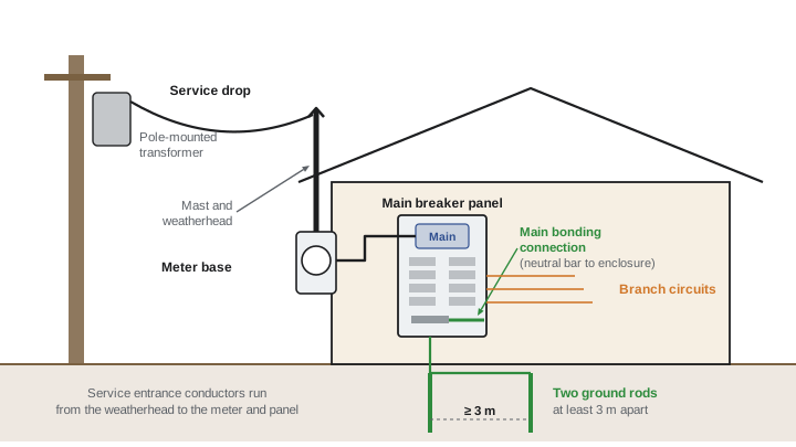
- Service drop (overhead) or service lateral (underground): the utility's conductors to the building. Ownership and responsibility boundaries vary by utility.
- Service entrance conductors: from the point of connection to the service equipment, often run through a mast or conduit.
- Meter base (meter socket): supplied and installed by the electrician, to the utility's specification, holding the utility's revenue meter.
- Service equipment: the main disconnecting means and overcurrent protection, usually a main breaker in the panelboard ("main-breaker panel"), or a separate disconnect where the panel is remote or the code requires it.
- Grounding electrode system and grounding electrode conductor, and the main bonding connection between the neutral and the service enclosure.
Overhead and underground supply
An overhead service uses a service drop from the utility pole to an attachment point on the house, often a mast that passes through the roof eave to gain height. The code and the utility set minimum clearances for the drop above roofs, ground, driveways and streets, and from windows, decks and swimming pools, and the mast must be strong enough to resist the drop's tension (masts are typically rigid metal conduit of at least the size the utility specifies, braced if tall).
In Canada, clearances for overhead service conductors are set by the Canadian Electrical Code (Section 6 and the clearance tables it references) together with the supply utility's service standards, which are often more specific. Utilities publish service guides with mast heights, attachment details and meter locations; follow the local utility's current guide and obtain its approval before energizing.
Underground services run the lateral in conduit or as direct-buried cable from a pad-mounted transformer or a pedestal, entering the meter base from below. They avoid the clearance and storm problems of overhead drops and are standard in new subdivisions. Conduits must be deep enough to protect the conductors, sealed where they enter the building to keep out water and gas, and arranged so that frost heave does not damage the meter base (expansion fittings are common in cold climates).
Sizing service conductors
Service conductors must carry the calculated load from Lesson 1 and be protected by the service overcurrent device. In general they are sized from the ampacity tables used in ELEC-120, at the 75 °C column for typical terminations. Because the diversity of household loads means a dwelling's service conductors rarely carry their rated current for long, both codes allow smaller conductors for dwelling services than the general tables would give.
The Canadian Electrical Code permits service and feeder conductors for single dwellings to be sized from a dedicated table (Table 39) rather than the general ampacity tables, recognizing the diversity of residential loads. Copper and aluminium conductors of the sizes in that table may be used for the corresponding service ratings, provided the calculated load does not exceed the rating and the conditions of the rule are met. Aluminium conductors are widely used for services and must be terminated in equipment marked for aluminium, with the termination torqued to the manufacturer's value.
Worked problem
Service conductors for a 200 A service
A house has a calculated load of 150 A and receives a 200 A service. Where would the electrician look for the permitted conductor sizes, and what other checks apply?
Show solution
- Because this is a single dwelling, the dwelling service table permits conductor sizes for a 200 A service smaller than the general ampacity tables would require.
- The calculated load (150 A) does not exceed the 200 A rating, so the table applies; confirm the termination temperature rating and that the conductors are marked for the installation (for example, in a raceway or as cable).
- Check voltage drop on long underground laterals, and the utility's requirements for the meter base and conductor entry.
Answer: Use the dwelling service table for the 200 A conductor size in copper or aluminium, verify terminations, installation conditions and voltage drop, and follow the utility's meter base standard.
Panelboards
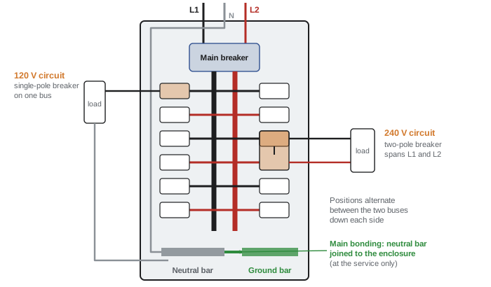
The panelboard (load centre) distributes power to branch circuits. A typical residential panel has two bus bars, one for each ungrounded conductor, arranged so that alternate breaker positions connect to alternate buses: a single-pole breaker connects to one bus and supplies 120 V circuits; a two-pole breaker spans both and supplies 240 V circuits. A neutral bar collects the neutrals, and a separate equipment grounding (bonding) bar collects the equipment grounding conductors.
Choosing a panel involves its ampere rating (at least the service or feeder rating), its number of circuit positions (allow plenty of spare spaces: heat pumps, EV chargers and solar are often added later), its short-circuit current rating (which must be at least the fault current available from the utility, commonly 10 kA for residential, but larger near big transformers), and the breaker types it accepts. Breakers must be those listed for the panel; mixing brands or using "classified" substitutes only where specifically permitted.
The Canadian Electrical Code requires a minimum number of branch circuit positions in the panelboard of a single dwelling, so that future circuits can be added without overcrowding, and requires two-pole breakers or identified handle ties for multi-wire branch circuits so that both ungrounded conductors are disconnected together. Panels must be accessible and must not be located in bathrooms or clothes closets.
Worked problem
Balancing a panel
A panel's 120 V loads total 42 A on L1 and 18 A on L2 at the busiest time of day, plus 240 V loads drawing 50 A. What are the currents in L1, L2 and the neutral? How could the panel be improved?
Show solution
- L1: \(42 + 50 = 92\) A. L2: \(18 + 50 = 68\) A.
- Neutral: the difference of the 120 V loads, \(42 - 18 = 24\) A (240 V loads put no current on the neutral).
- Moving about 12 A of 120 V load from L1 to L2 would give 30 A on each, so L1 = L2 = 80 A and the neutral current would fall to near zero.
Answer: L1 carries 92 A, L2 68 A and the neutral 24 A. Balancing the 120 V circuits between the two buses lowers the maximum conductor current from 92 A to 80 A and the neutral current toward zero, reducing losses and voltage drop and freeing capacity.
Open neutrals
If the service neutral is lost (from a corroded connection at the meter base or a broken drop), 120 V loads on the two buses are left in series across 240 V. The bus with the lighter load sees more than 120 V, sometimes nearly 240 V, and the heavier one less, which can destroy electronics and appliances and cause lights to flicker bright and dim as loads change. Symptoms such as lights brightening when a large 120 V load starts are a warning that should be investigated at once. Neutral connections at the service must be tight, correctly torqued and protected from corrosion.
Grounding and bonding at the service
ELEC-120 explained the two separate jobs of grounding (connecting the system to earth to limit voltages from lightning, line surges and contact with higher-voltage lines) and bonding (connecting metal parts so that a fault clears quickly and no dangerous touch voltages remain). At a residential service:
- The neutral is connected to the grounding electrode system and bonded to the service enclosure at one point only, the service equipment. Downstream of the service, the neutral and the equipment grounding conductors are kept separate, so that normal neutral current does not flow on metal enclosures and grounding conductors. A subpanel in the house or a detached garage therefore has an isolated neutral bar and a separate bonded ground bar, fed by a four-wire feeder.
- The grounding electrode system for a typical dwelling consists of manufactured ground rods (at least two, spaced at least 3 m apart, driven to their full length) or a ground plate, a concrete-encased electrode (field-assembled rebar or a bare copper conductor in the footing) where one is available, or a metal water pipe in contact with the earth for the required length. The grounding conductor is sized from the code table for the service conductor size, typically 6 AWG copper for residential services up to about 200 A, and is protected from damage.
- Metal water piping and other metal piping systems, such as gas piping where required, are bonded to the service so that they cannot become energized at a different potential from the electrical system.
Worked problem
Why the neutral is bonded only at the service
A subpanel in a garage is fed by a three-wire feeder (two hots and a neutral) and its neutral is bonded to its enclosure. A 120 V load in the garage draws 15 A. Where does the neutral current flow, and what is the hazard?
Show solution
- With the neutral bonded at the subpanel, returning current divides between the neutral conductor and every parallel metal path back to the service: conduit, cable armour, water piping and grounding conductors.
- Some of the 15 A flows on these metal parts continuously, and if the neutral conductor opens, all of it does, energizing metal parts.
Answer: Neutral current flows on metal that people touch and on grounding paths intended only for faults, creating shock risk, heating and interference. The fix is a four-wire feeder (adding an equipment grounding conductor), an isolated neutral bar in the subpanel and its bonding screw or strap removed.
Location and working space
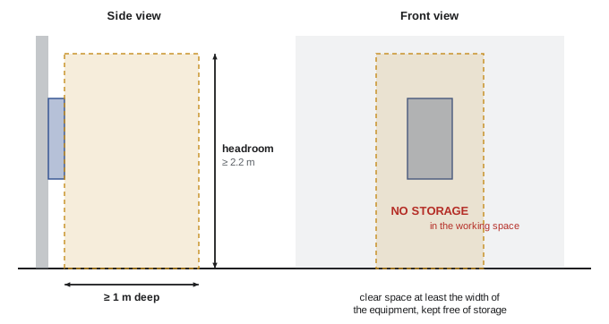
Service equipment and panelboards must be readily accessible and have clear working space in front of them so that a person can operate and maintain them safely.
The Canadian Electrical Code requires working space of at least 1 m in front of electrical equipment such as panelboards, with adequate headroom and lighting, kept clear of storage. The service box is usually located as close as practical to the point where the service conductors enter the building, and panelboards are not permitted in bathrooms, clothes closets or other locations where they would be exposed to damage or hard to reach. Many utilities also set a maximum length of unfused service conductor inside the building.
Lesson 10 returns to the service when solar, batteries, generators and EV chargers are added, and Lesson 11 covers service upgrades and panel replacements in existing homes.
Common mistakes
MistakeBonding the neutral to the enclosure in a subpanel.
InsteadBond neutral to ground only at the service; subpanels have isolated neutrals and four-wire feeders.
MistakeUsing breakers of a different brand in a panel.
InsteadUse only breakers listed for that panel (or classified breakers explicitly permitted for it).
MistakeLeaving aluminium terminations untorqued or without anti-oxidant where required.
InsteadTorque to the manufacturer's value and follow the termination instructions for aluminium.
MistakeLoading all 120 V circuits on one bus.
InsteadBalance 120 V loads between L1 and L2 to reduce conductor and neutral current.
MistakeLocating a panel in a clothes closet or bathroom, or storing items in front of it.
InsteadKeep panels accessible with the required clear working space.
MistakeIgnoring the available fault current.
InsteadCheck that the panel and breakers have short-circuit ratings at least equal to the available fault current.
Summary and key terms
- Residential services are single-phase 120/240 V three-wire from a centre-tapped transformer.
- Parts: service drop or lateral, service entrance conductors, meter base, service equipment (main disconnect and overcurrent protection), grounding electrode system and main bonding connection.
- Overhead drops need code and utility clearances; underground laterals need depth, sealing and frost protection.
- Single-dwelling service conductors may be sized from the dwelling table (Table 39), recognizing diversity.
- Panels: two alternating buses give 120 V and 240 V circuits; check ampere rating, spaces, short-circuit rating and listed breakers.
- Balance 120 V loads; an open service neutral causes dangerous over- and under-voltages.
- Neutral and ground are bonded only at the service; subpanels have isolated neutrals and four-wire feeders.
- Grounding electrodes: typically two rods 3 m apart, plate, concrete-encased electrode or water pipe; working space at least 1 m.
- Service drop
- Overhead utility conductors from the pole to the building.
- Service lateral
- Underground utility conductors to the building.
- Service entrance conductors
- Conductors from the point of connection to the service equipment.
- Meter base
- The socket that holds the utility's revenue meter.
- Service equipment
- The main disconnecting means and overcurrent protection for the building.
- Panelboard
- An assembly of buses and overcurrent devices distributing power to circuits.
- Two-pole breaker
- A breaker that connects to both ungrounded buses, supplying 240 V.
- Multiwire branch circuit
- A circuit with two ungrounded conductors sharing one neutral.
- Main bonding connection
- The connection between the neutral and the service enclosure at the service.
- Grounding electrode
- A conducting object that connects the electrical system to the earth.
- Open neutral
- A broken neutral connection that causes unequal voltages on 120 V loads.
- Short-circuit current rating
- The maximum fault current equipment can safely withstand or interrupt.
- Working space
- The clear area required in front of electrical equipment.
Practice problems
Work each problem on paper first, then reveal the answer to check.
What are the voltages between L1 and L2, and between either and neutral, in a residential service?
Show answer
240 V between L1 and L2; 120 V from either to neutral.
Where are permitted conductor sizes for a single-dwelling service found?
Show answer
In the dwelling service table (Table 39), which permits smaller conductors than the general ampacity tables.
L1 carries 30 A of 120 V load and L2 carries 45 A of 120 V load. What is the neutral current?
Show answer
15 A (the difference).
A house has a 30 A, 240 V water heater as its only load besides balanced lighting. What does the water heater add to the neutral?
Show answer
Nothing: a 240 V load uses only L1 and L2.
With an open service neutral, 120 V loads of 10 Ω on L1 and 30 Ω on L2 are in series across 240 V. What voltage does each see?
Show answer
Current 240/40 = 6 A; L1 load 60 V, L2 load 180 V: the lightly loaded side sees 180 V.
Why does a detached garage subpanel need a four-wire feeder?
Show answer
So the neutral can be isolated from the enclosure and an equipment grounding conductor carries fault current, keeping normal neutral current off metal parts.
How many ground rods are typically required, and how far apart?
Show answer
At least two, spaced at least 3 m apart, driven to full length.
A panel is rated 10 kA but the utility reports 14 kA available fault current. Is it acceptable?
Show answer
No: equipment must be rated for at least the available fault current; use a higher-rated panel or a series-rated combination as permitted.
What clear working space is required in front of a residential panel?
Show answer
At least 1 m in front, with headroom and lighting, kept clear.
Why must breakers be listed for the panel they are installed in?
Show answer
Bus contact design, ratings and testing are specific to the panel; mismatched breakers can overheat, fail to clear faults or void the listing.
Lesson quiz · 5 questions
Score 60% or more to complete this lesson.
Create a free account to save your progress, take quizzes and earn a certificate.