
ELEC-120 · Lesson 4 of 12 · 30 min
Conductor sizing and ampacity
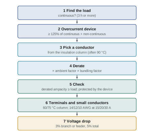
Choosing the right conductor size is the calculation electricians make most often. Too small, and the conductor overheats: insulation ages quickly, connections loosen, and in the worst case a fire starts inside a wall. Too large, and the job costs more and the conductors may not fit the terminals. The code gives a clear procedure: find the load, choose the overcurrent protection, select a conductor whose ampacity suits both after allowing for its installation conditions, check the terminations, and confirm the voltage drop. This chapter walks through each step with worked examples.
The ampacity rules are in Section 4 of the CEC (Rule 4-004 and the related rules), with the ampacity values in Tables 1 to 4 and the correction factors in Tables 5A to 5D. Overcurrent protection of conductors is in Section 14 and circuit loading in Section 8.
What limits a conductor's current
A conductor carrying current heats up because of its resistance (\(P = I^2R\), from ELEC-110). It reaches a steady temperature when the heat generated equals the heat it can shed to its surroundings. Ampacity is the current at which that steady temperature equals the maximum rating of the insulation. It therefore depends on:
- The conductor size and material: larger conductors have less resistance; aluminum has about 1.6 times the resistance of copper of the same size, so it needs a larger size for the same current.
- The insulation temperature rating, usually 60 °C, 75 °C or 90 °C.
- How easily heat escapes: a single conductor in free air cools better than several bundled in a raceway or cable.
- The ambient temperature: a hot attic or a boiler room leaves less margin before the conductor reaches its limit.
Common insulation types include RW90 (cross-linked polyethylene, 90 °C, wet and dry), T90 Nylon (90 °C dry, thermoplastic with nylon jacket, used in conduit), TWU and RWU (underground), and cables such as NMD90 (non-metallic sheathed cable for dwellings), AC90 (armoured cable) and TECK90 (armoured, jacketed cable for industrial use).
The ampacity tables
Table 2 gives the ampacity of copper conductors with not more than three current-carrying conductors in a raceway or cable (or directly buried), based on an ambient temperature of 30 °C, with separate columns for 60 °C, 75 °C and 90 °C insulation. Table 1 covers single copper conductors in free air, and Tables 3 and 4 do the same for aluminum. A few representative values for copper in the 75 °C column of Table 2 are shown below; always use the table in your adopted edition.
| Copper size | 60 °C | 75 °C | 90 °C |
|---|---|---|---|
| 14 AWG | 15 A | 20 A | 25 A |
| 12 AWG | 20 A | 25 A | 30 A |
| 10 AWG | 30 A | 35 A | 40 A |
| 8 AWG | 40 A | 50 A | 55 A |
| 6 AWG | 55 A | 65 A | 75 A |
| 4 AWG | 70 A | 85 A | 95 A |
| 2/0 AWG | 145 A | 175 A | 195 A |
| 4/0 AWG | 195 A | 230 A | 260 A |
Small conductors
For the small copper conductors used in most branch circuits, the code limits the overcurrent protection regardless of the higher table values: 14 AWG copper to 15 A, 12 AWG to 20 A and 10 AWG to 30 A (Rule 14-104, with limited exceptions such as some motor and heating circuits). So a 12 AWG conductor rated 25 A at 75 °C is still protected at 20 A.
Which column?
A conductor with 90 °C insulation does not automatically get the 90 °C ampacity. The whole circuit is only as good as its weakest point, and the terminations on breakers, panels and devices are usually rated 60 °C or 75 °C. The rule of thumb used by both codes:
- Equipment rated 100 A or less, or marked for 14 to 1 AWG conductors, generally uses the 60 °C column unless the equipment is marked for 75 °C.
- Equipment rated over 100 A, or marked for conductors larger than 1 AWG, generally uses the 75 °C column.
- The 90 °C column can be used as the starting point for correction and adjustment calculations, as long as the final ampacity does not exceed the termination column.
These limits come from Rule 4-006 (temperature limitations at terminations) and the equipment markings. Most modern breakers and panelboards are marked for 75 °C, but check.
Correction and adjustment factors
When the conditions are worse than those assumed by the table, the ampacity must be reduced:
- Ambient temperature above 30 °C: multiply by the correction factor from Table 5A. For 90 °C insulation, the factor is about 0.91 at 40 °C and 0.87 at 45 °C; for 75 °C insulation, about 0.88 at 40 °C.
- More than three current-carrying conductors in a raceway or cable: multiply by the factor from Table 5C: 80% for four to six conductors and 70% for seven or more up to the next step in the table. Neutrals that carry only the unbalanced current of a balanced circuit, and bonding conductors, are not counted.
Both factors apply together when both conditions exist. Start from the column of the insulation rating (usually 90 °C), apply the factors, then check the result against the termination column and the small-conductor limits.
Worked problem
A continuous branch circuit load
A fixed electric heater draws 24 A and runs for hours at a time. Conductors are copper in conduit with two other conductors, at 30 °C. Select the breaker and conductor size.
Show solution
- The load is continuous. With a standard breaker, the load may be at most 80% of the rating (Rule 8-104): rating ≥ \(24/0.8 = 30\) A. Choose a 30 A breaker.
- The conductor must also be rated at least 30 A in the termination column (75 °C): 10 AWG copper is 35 A at 75 °C.
- Small-conductor limit: 10 AWG may be protected at up to 30 A. ✓
Answer: 30 A breaker with 10 AWG copper. A 12 AWG conductor (25 A at 75 °C, and limited to 20 A protection) would be too small.
Worked problem
Bundling and a hot ceiling space
Nine current-carrying 12 AWG copper conductors with 90 °C insulation share a conduit through a ceiling space at 40 °C. Can they be protected at 20 A? What about 10 AWG?
Show solution
- Start from the 90 °C column: 12 AWG = 30 A.
- Ambient correction at 40 °C: 0.91. Bundling (7–9 conductors): 0.70.
- Adjusted ampacity: \(30 \times 0.91 \times 0.70 = 19.1\) A, which is less than 20 A.
- For 10 AWG: \(40 \times 0.91 \times 0.70 = 25.5\) A, which is above 20 A; and the 75 °C termination value (35 A) is not exceeded.
Answer: The 12 AWG conductors cannot be protected at 20 A in these conditions (19.1 A < 20 A), but 10 AWG can. Alternatively, splitting the circuits into two raceways (four to six conductors, factor 0.80) gives \(30 \times 0.91 \times 0.80 = 21.8\) A, enough for 12 AWG on 20 A breakers.
Overcurrent protection and standard sizes
Overcurrent devices come in standard ratings (15, 20, 25, 30, 35, 40, 45, 50, 60, 70, 80, 90, 100, 110, 125, 150, 175, 200, 225 A and so on). The general principle is that a conductor must be protected at no more than its ampacity. When a conductor's ampacity falls between standard ratings, the code (Rule 14-104 and related rules) allows, under specific conditions, the next higher standard rating; check the conditions carefully before using it.
Worked problem
Sizing a feeder
A feeder to a subpanel serves 140 A of continuous load. Copper conductors in conduit, three current-carrying conductors, 30 °C, terminations rated 75 °C. Size the breaker and the conductors.
Show solution
- Continuous load on a standard breaker: rating ≥ \(140/0.8 = 175\) A. Choose a 175 A breaker.
- Conductor ampacity at 75 °C must be at least 175 A: 2/0 copper = 175 A.
- No correction or adjustment applies (30 °C, three conductors).
Answer: 175 A breaker with 2/0 copper conductors. In aluminum, the larger size 4/0 (about 180 A at 75 °C) would be needed.
Parallel conductors
For large feeders and services, a single conductor can become unmanageably large. Both codes allow conductors of 1/0 AWG and larger to be run in parallel, with each phase made up of two or more conductors that are the same length, material, size, insulation type and termination method, so that the current divides equally. A 600 A feeder might use two sets of 350 kcmil copper, each set in its own raceway with all phases and the neutral together, to avoid heating from induced currents in metal raceways.
Voltage drop
Ampacity keeps conductors cool; it does not guarantee that the load receives adequate voltage. On long runs, the voltage drop calculated in ELEC-110 may require a larger conductor than ampacity alone.
Rule 8-102 limits the voltage drop in an installation to 5% from the supply side of the consumer's service to the point of utilization, and 3% in a feeder or branch circuit. These limits are mandatory in the CEC.
Worked problem
When voltage drop decides the size
A 120 V, 16 A load is 40 m from the panel. 12 AWG copper has a resistance of about 6.5 Ω/km at operating temperature. Is 12 AWG acceptable for a 3% limit? What about 10 AWG (about 4.1 Ω/km)?
Show solution
- 12 AWG: \(V_d = 2 \times 0.040 \times 6.5 \times 16 = 8.3\) V, which is 6.9% of 120 V. Too high.
- 10 AWG: \(V_d = 2 \times 0.040 \times 4.1 \times 16 = 5.2\) V, or 4.4%. Still above 3%.
- Allowed drop: 3% of 120 V = 3.6 V, so the resistance must be at most \(3.6/(2 \times 0.040 \times 16) = 2.8\) Ω/km. 8 AWG copper (about 2.6 Ω/km) gives 3.3 V, or 2.8%.
Answer: 12 AWG satisfies ampacity (20 A breaker, 16 A load) but gives about 7% drop; even 10 AWG exceeds 3%. 8 AWG copper (or a higher circuit voltage, or a closer panel) is needed. On long runs, voltage drop often governs.
Lesson 5 continues with the overcurrent devices that protect these conductors, including interrupting ratings, selective coordination and tap rules.
Common mistakes
MistakeUsing the 90 °C ampacity directly because the wire is rated 90 °C.
InsteadUse 90 °C only as the starting point for derating; the result cannot exceed the termination (60 °C or 75 °C) column.
MistakeForgetting the small-conductor limits.
Instead14, 12 and 10 AWG copper are limited to 15, 20 and 30 A protection.
MistakeIgnoring bundling or hot ambient conditions.
InsteadApply both ambient and bundling factors when they exist.
MistakeCounting the bonding/equipment grounding conductor as current-carrying.
InsteadIt carries current only during faults and is not counted for bundling.
MistakeSizing long runs on ampacity alone.
InsteadCheck voltage drop; it often requires a larger conductor.
Summary and key terms
- Ampacity is the continuous current a conductor can carry without exceeding its insulation temperature, depending on size, material, insulation, installation and ambient.
- Ampacities are in Tables 1–4 (Table 2 for copper in raceways and cables); correction factors in Tables 5A–5D.
- Small copper conductors are limited to 15 A (14 AWG), 20 A (12 AWG) and 30 A (10 AWG) protection.
- Terminations usually limit the usable column to 60 °C or 75 °C; 90 °C ratings are a starting point for derating.
- Apply ambient correction and bundling adjustment (80% for 4–6, 70% for 7–9 current-carrying conductors) together.
- Size overcurrent devices at 125% of continuous load (load ≤ 80% of rating) and protect conductors at no more than their ampacity, using standard ratings.
- Parallel conductors (1/0 and larger) must be identical; voltage drop (3% branch or feeder, 5% total) often governs long runs.
- Ampacity
- The current a conductor can carry continuously under its conditions of use without exceeding its temperature rating.
- Insulation temperature rating
- The maximum continuous temperature an insulation is designed for, such as 60, 75 or 90 °C.
- Termination temperature rating
- The temperature rating of a terminal, which limits the ampacity column that may be used.
- Correction factor
- A multiplier reducing ampacity for ambient temperatures above the table basis.
- Adjustment factor
- A multiplier reducing ampacity for more than three current-carrying conductors together.
- Current-carrying conductor
- A conductor that carries normal load current, counted for bundling adjustments.
- Small-conductor rule
- The limit on overcurrent protection for 14, 12 and 10 AWG copper.
- Standard rating
- One of the standard ampere ratings of fuses and breakers.
- Continuous load
- A load running at maximum current for three hours or more.
- Parallel conductors
- Two or more identical conductors connected together to act as one larger conductor.
- kcmil
- Thousand circular mils, the unit for conductor sizes above 4/0 AWG.
- Voltage drop
- The loss of voltage along conductors due to their resistance.
Practice problems
Work each problem on paper first, then reveal the answer to check.
What is the 75 °C ampacity of 8 AWG copper (not more than three conductors, 30 °C)?
Show answer
50 A.
A 10 AWG copper conductor rated 90 °C: what is the maximum breaker size for a general-purpose branch circuit?
Show answer
30 A, by the small-conductor limit.
A continuous load of 36 A: what minimum standard breaker is required?
Show answer
36 × 1.25 = 45 A, so a 45 A breaker.
Six current-carrying 10 AWG copper 90 °C conductors share a raceway at 30 °C. What is the adjusted ampacity?
Show answer
40 × 0.80 = 32 A (limited to 30 A protection for 10 AWG).
Three 6 AWG copper 90 °C conductors run through a 45 °C space. What is their corrected ampacity?
Show answer
75 × 0.87 = 65.3 A, within the 75 °C value of 65 A for the termination check (use 65 A).
Nine 12 AWG 90 °C copper conductors at 30 °C: can each be protected at 20 A?
Show answer
30 × 0.70 = 21 A ≥ 20 A, so yes at 30 °C (but not at 40 °C, where it falls to 19.1 A).
A feeder carries 100 A of continuous load and 20 A of non-continuous load. What is the minimum standard breaker?
Show answer
1.25 × 100 + 20 = 145 A, so 150 A.
For the previous feeder, what minimum copper size is needed at 75 °C (three conductors, 30 °C)?
Show answer
At least 150 A: 1/0 copper (150 A at 75 °C).
Why must parallel conductors be the same length, size and material?
Show answer
So that they have equal impedance and share current equally; otherwise one set carries more than its share and overheats.
What voltage drop limits does Rule 8-102 set?
Show answer
3% for a feeder or branch circuit and 5% overall from the service to the load.
Lesson quiz · 5 questions
Score 60% or more to complete this lesson.
Create a free account to save your progress, take quizzes and earn a certificate.