
ELEC-120 · Lesson 12 of 12 · 33 min
Applying the code: permits, inspections and a worked installation
The earlier lessons treated the code one topic at a time: definitions, branch circuits, conductor sizing, overcurrent protection, wiring methods, devices, panelboards, grounding and special locations. On a real job they all apply at once, and the code is only one part of a process that also includes planning, permits, inspections and documentation. This final lesson follows that process from start to finish and then works through a complete small installation, a detached garage workshop fed from a house, checking every decision against the rules covered in the course.
The job from start to finish
A typical electrical installation passes through these stages:
- Scope and design: what loads, where, and what supply is available. For larger projects an engineer prepares stamped drawings; for small jobs the electrician lays out the work.
- Permit: the electrical contractor applies to the inspection authority before work starts, describing the work and paying a fee.
- Rough-in: boxes, raceways and cables are installed before walls and ceilings are closed, and a rough-in inspection is requested.
- Service connection: where a new or altered service is involved, the inspector authorizes the utility to connect.
- Finish: devices, luminaires and equipment are installed and terminated, circuits are labelled and tested.
- Final inspection and close-out: the inspector checks the completed work, and the permit is closed. Defects found are listed on a deficiency or correction notice that must be addressed.
In Canada, electrical permits are issued by the provincial or territorial inspection authority (for example, Technical Safety BC, the Electrical Safety Authority in Ontario, or the Régie du bâtiment du Québec through its own rules), or by certain municipalities with delegated authority. In most provinces only licensed electrical contractors may take out permits for others, while homeowners may be permitted to do work on their own single-family dwelling under a homeowner permit.
Inspectors do not design the installation; they verify that it complies. The responsibility for compliance stays with the installer, and the inspector may require any part of the work to be opened up or corrected.
Reading plans and specifications
On commercial work the design is communicated through drawings and specifications. Electrical drawings use standard symbols for receptacles, switches, luminaires, panels and home runs; a home run arrow with a label such as "LP-1, 5, 7" means the circuit returns to panel LP-1, circuits 5 and 7. Panel schedules list each circuit, its load and its breaker; one-line diagrams show the distribution from service to panels. The specifications state the materials and methods (for example, EMT in exposed areas, copper conductors only, minimum 12 AWG).
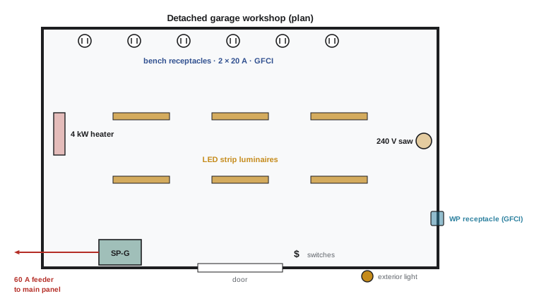
Where drawings and the code disagree, the code is the minimum: a design may exceed it but never fall below it. Where drawings are silent, the code still applies.
Worked installation: a detached garage workshop
A homeowner wants a detached garage converted into a workshop, 15 m from the house. The house has a 200 A, 120/240 V single-phase service with spare panel spaces. The workshop will have:
- Bench receptacles: six duplex receptacles on two 20 A circuits.
- A 240 V table saw rated 13 A at 240 V (a 3 hp motor) on its own circuit.
- A 240 V electric heater, 4 kW.
- LED lighting: about 300 W, with an exterior wall light and an exterior weatherproof receptacle.
- A future electric vehicle charger is not included now.
Step 1: Estimate the load and size the feeder
A simple estimate adds the larger loads and a reasonable allowance for receptacles. Lighting 300 W; receptacle circuits allowance 3,000 W; table saw \(240 \times 13 = 3{,}120\) W; heater 4,000 W (a continuous load).
Worked problem
Feeder load
Find the total load in amperes at 240 V, treating the heater and lighting as continuous loads.
Show solution
- Continuous loads at 125%: \((4{,}000 + 300) \times 1.25 = 5{,}375\) W.
- Other loads: \(3{,}000 + 3{,}120 = 6{,}120\) W.
- Total: \(11{,}495\) W; current \(11{,}495/240 = 47.9\) A.
Answer: About 48 A, so a 60 A feeder gives margin for future additions (other than the EV charger, which would need its own load calculation). In practice a formal calculation method for detached buildings, or the designer's judgment, may apply; this estimate shows the logic.
For a 60 A feeder at 75 °C terminations, 6 AWG copper (65 A at 75 °C) is typical. The house panel must also be checked: adding about 48 A to the existing calculated load must not exceed the 200 A service (a full dwelling load calculation would be done here, using the methods introduced in Lesson 3).
Step 2: Check voltage drop
Worked problem
Feeder voltage drop
The feeder route is 20 m one way (15 m plus the runs inside each building). 6 AWG copper has about 1.32 Ω/km. Find the voltage drop at 48 A at 240 V.
Show solution
- Loop resistance: \(2 \times 20 \times 0.00132 = 0.0528\) Ω.
- Drop: \(48 \times 0.0528 = 2.5\) V, or \(2.5/240 = 1.1\%\).
Answer: About 1.1%, well within the usual guideline of 3% for a feeder (5% total), leaving room for branch-circuit drop in the workshop.
Step 3: Choose the wiring method
The feeder runs underground between the buildings. Options include direct-buried cable rated for the purpose, or conductors in rigid PVC conduit. With conduit, the conductors can be replaced or upsized later, which suits a future EV charger. Burial depth depends on the method and location (Lesson 6). Where the conduit rises out of the ground it needs protection from damage, and an expansion fitting where frost heave or temperature change could move it. Conductors in underground raceways are in a wet location, so they must be rated for wet locations (for example, RW90 or THWN-2; Lesson 10).
Worked problem
Conduit fill for the feeder
The feeder has two 6 AWG ungrounded conductors, one 6 AWG neutral (the heater and saw are 240 V, but the receptacles and lights need 120 V) and one 10 AWG bonding conductor, all THWN-2. Approximate areas: 6 AWG 46.8 mm², 10 AWG 13.6 mm². What size of rigid PVC conduit is needed if the 40% fill area of 27 mm (1 in) PVC is about 211 mm² and of 21 mm (3/4 in) is about 120 mm²?
Show solution
- Total area: \(3 \times 46.8 + 13.6 = 154.0\) mm².
- 21 mm: 120 mm² is too small. 27 mm: 211 mm² is enough.
Answer: 27 mm (1 in) PVC is the minimum; many electricians would choose 35 mm (1-1/4 in) to allow future upsizing for an EV charger. The bonding conductor is sized from the 60 A feeder overcurrent device (Lesson 9).
Step 4: Grounding and bonding at the detached building
The feeder includes an equipment bonding conductor, so the garage subpanel is treated like any subpanel: its neutral bar is isolated from the enclosure, and the bonding conductor connects to the enclosure and the equipment grounding bar. A detached building supplied by a feeder also generally needs its own grounding electrode (such as ground rods) connected to the subpanel's grounding bar, so that lightning and other surges have a local path to earth. The building also needs a disconnecting means at the point where the feeder enters (Lesson 8); the subpanel's main breaker can serve, if the panel is suitable for the purpose.
The CEC requires a grounding electrode at a separate building supplied by a feeder, with the bonding conductor run with the feeder.
Step 5: Branch circuits
Inside the workshop, the subpanel supplies:
- Two 20 A, 120 V bench receptacle circuits in 12 AWG copper, with ground-fault protection because garages and workshops are locations where it is required (Lesson 10). The exterior weatherproof receptacle also needs ground-fault protection and a weatherproof in-use cover.
- A 240 V table saw circuit sized for the motor, whose conductors must carry 125% of its full-load current: a 13 A motor needs conductors rated at least \(1.25 \times 13 = 16.25\) A, so 12 AWG, with overcurrent protection chosen for motor starting, and a disconnect within sight of the saw (the plug and receptacle may serve as the disconnect for a cord-connected tool).
- A 240 V heater circuit: \(4{,}000/240 = 16.7\) A continuous, times 1.25 = 20.8 A, so a 25 A breaker with 10 AWG copper (or as the heater's nameplate requires).
- A lighting circuit at 15 A, with switches at the entrance door and the exterior light.
Worked problem
Panel space and balance
List the breaker spaces needed and estimate the load on each leg at 120/240 V, with the receptacle allowance split evenly between the two 120 V circuits (one on each leg) and the lighting on leg A.
Show solution
- Spaces: two 2-pole breakers (saw, heater) use 4 spaces; three 1-pole breakers (two receptacle, one lighting) use 3 spaces; total 7, so an 8- or 12-space panel.
- Leg A: saw 13 A + heater 16.7 A + receptacles 12.5 A + lighting 2.5 A = 44.7 A.
- Leg B: 13 + 16.7 + 12.5 = 42.2 A.
Answer: Seven spaces; legs carry about 45 A and 42 A, well balanced. A 12-space panel leaves room for future circuits, a common practical choice.
Step 6: Inspection checklist
Before calling for inspection, a careful electrician checks the work against the issues inspectors most often find:
| Item | What to check | Lesson |
|---|---|---|
| Permit and labels | Permit posted; panel directory filled in; feeder breaker labelled at the house | 1, 8 |
| Conductors | Sizes match breakers; terminal temperature ratings respected | 4, 5 |
| Boxes and raceways | Box fill, conduit fill, bends, supports, bushings, burial depth | 6 |
| Devices | Ground-fault protection where required, tamper-resistant receptacles where required, in-use covers outdoors | 7, 10 |
| Panel | Neutral isolated, bonding conductor landed, working space clear, unused openings closed | 8 |
| Grounding | Electrode and conductor at the garage; bonding of metal raceways and boxes | 9 |
| Special | Wet-location conductors underground; cords not used as permanent wiring | 10 |
Testing and documentation
Before energizing, and as part of handing over the work, the electrician tests the installation:
- Continuity of bonding conductors and the absence of unintended neutral-to-ground connections at the subpanel.
- Insulation resistance testing of the feeder (for example, at 500 V or 1,000 V DC with a megohmmeter), looking for values in the megohms or higher.
- Polarity and correct wiring of every receptacle, using a plug-in tester, and operation of every ground-fault and arc-fault device using its test button.
- Voltage at the subpanel under load, and a check that the heater and saw run correctly.
Finally, the panel directory is completed with clear descriptions ("Bench receptacles, north wall"), and the homeowner is shown the disconnect, the test buttons and the locations of devices.
Worked problem
Reading an insulation test
A megohmmeter test of the new feeder at 500 V DC reads 850 MΩ between each conductor and ground. What leakage current is that, and is it acceptable?
Show solution
- Leakage: \(I = V/R = 500 / (850 \times 10^{6}) = 0.59\) µA.
Answer: Less than a microampere: excellent insulation for a new installation. Readings below about 1 MΩ, or that fall sharply over time, would indicate damage, moisture or a nicked conductor that must be found before energizing.
Code changes and continuing learning
The code changes with every edition, every three years, as new technology appears and incident data reveal new hazards. Recent editions have expanded ground-fault and arc-fault protection, added rules for energy storage systems, electric vehicle charging, solar installations, Power over Ethernet and DC distribution, and reorganized whole sections. A working electrician therefore keeps learning: reading the changes summary for each new edition, attending update seminars, and checking which edition and amendments the local authority enforces. Courses later in this program cover particular systems in more depth: industrial controls and motors, renewable energy, and data centre power.
The code itself states that it is a minimum standard for safety. Good work often goes beyond it: larger conduits for future cables, spare panel spaces, circuits that are clearly labelled and drawings that are kept up to date. These choices cost little at installation and make the next electrician's work safer and faster.
Common mistakes
MistakeStarting work before the permit is issued.
InsteadObtain the permit first; some authorities can require finished work to be opened up.
MistakeBonding the neutral to the enclosure in a detached building's subpanel.
InsteadKeep the neutral isolated; bond the enclosure with the feeder's bonding conductor and add a local electrode.
MistakeUsing dry-location conductors in an underground conduit.
InsteadUnderground raceways are wet locations; use wet-rated conductors.
MistakeForgetting the house service when adding a large feeder.
InsteadRecalculate the dwelling load to confirm the service can carry it.
MistakeLeaving the panel directory blank.
InsteadLabel every circuit clearly; it is required and it protects the next person.
Summary and key terms
- A job runs from design and permit through rough-in and final inspection to close-out.
- The installer is responsible for compliance; the inspector verifies it.
- Drawings and specifications may exceed the code but never fall below it.
- A detached building feeder needs load, voltage-drop, fill, wet-location and grounding checks.
- Detached buildings need a disconnect, an isolated neutral, a bonding conductor and a local electrode.
- Testing and clear documentation complete the work; the code changes every edition.
- Permit
- Permission from the inspection authority to perform electrical work.
- Rough-in inspection
- Inspection of wiring before walls and ceilings are closed.
- Final inspection
- Inspection of completed work before the permit is closed.
- Deficiency notice
- A list of code violations found that must be corrected.
- Home run
- The wiring from the last outlet of a circuit back to the panel.
- Panel schedule
- A table listing each circuit, its load and its breaker.
- One-line diagram
- A simplified diagram of the power distribution system.
- Detached building
- A separate structure supplied by a feeder from another building.
- Insulation resistance test
- A high-voltage DC test of insulation using a megohmmeter.
- Panel directory
- The circuit labelling on a panelboard.
Practice problems
Work each problem on paper first, then reveal the answer to check.
Name the stages of a typical electrical job.
Show answer
Design, permit, rough-in and inspection, service connection, finish, final inspection and close-out.
Who is responsible for code compliance?
Show answer
The installer; the inspector verifies.
A home run labelled "LP-2, 9" means?
Show answer
The circuit returns to panel LP-2, circuit 9.
Continuous 3 kW heater plus 5 kW other load at 240 V: feeder current?
Show answer
(3,750 + 5,000)/240 = 36.5 A.
Voltage drop: 40 A, 25 m one way, 1.32 Ω/km?
Show answer
40 × 2 × 25 × 0.00132 = 2.64 V (1.1% at 240 V).
Why are underground conduit conductors wet-rated?
Show answer
Underground raceways are wet locations.
Is the neutral bonded to the enclosure in a detached building subpanel fed with a bonding conductor?
Show answer
No; it is isolated.
What else does a detached building need?
Show answer
A disconnecting means and a grounding electrode.
Leakage at 1,000 V with 500 MΩ insulation?
Show answer
2 µA.
How often is the code revised?
Show answer
Every three years.
Lesson quiz · 5 questions
Score 60% or more to complete this lesson.
Create a free account to save your progress, take quizzes and earn a certificate.