
ELEC-110 · Lesson 9 of 12 · 29 min
Magnetism and electromagnetism
Electricity and magnetism are two sides of the same phenomenon. Every current produces a magnetic field, and a changing magnetic field produces a voltage. These two facts make possible almost every machine an electrician installs: relays and contactors that switch circuits, solenoid valves, motors that turn pumps and fans, generators that supply the grid, transformers that change voltage, clamp meters that measure current without breaking the circuit, and the magnetic trip elements in circuit breakers. This lesson explains magnets and magnetic fields, the field around a current-carrying conductor and a coil, electromagnets and their uses, the force on a conductor in a magnetic field that drives motors, and electromagnetic induction, which drives generators and transformers.
Magnets and magnetic fields
A magnet has two poles, north and south. Like poles repel and unlike poles attract. The space around a magnet where its force acts is its magnetic field, pictured as lines of magnetic flux that leave the north pole and enter the south pole, forming closed loops. The closer the lines, the stronger the field. Iron filings sprinkled around a magnet line up along these flux lines.
Magnetic flux is measured in webers (Wb), and flux density, the flux per unit area, in teslas (T):
where \(B\) is flux density in teslas, \(\Phi\) is flux in webers and \(A\) is area in square metres. The Earth's field is about 0.00005 T (50 µT); a fridge magnet about 0.005 T; the iron core of a transformer or motor operates at about 1 T to 1.7 T; and an MRI scanner at 1.5 T to 3 T or more.
Materials respond to magnetic fields in different ways. Ferromagnetic materials, such as iron, nickel, cobalt and electrical steels, concentrate flux strongly, and are used in cores of motors, transformers and relays. Permanent magnets (ferrite, alnico, and powerful neodymium-iron-boron magnets) keep their magnetism; they are used in permanent magnet motors, generators in wind turbines, speakers and sensors. Most other materials, including copper, aluminum, plastics and air, are essentially non-magnetic.
The field around a current
In 1820, Hans Christian Ørsted noticed that a compass needle moved near a wire carrying current. Every current-carrying conductor is surrounded by circular magnetic field lines. The direction follows the right-hand rule: grip the conductor with your right hand, thumb pointing in the direction of conventional current (positive to negative), and your fingers curl in the direction of the field. The field weakens with distance from the conductor.
Worked problem
Field near a conductor
What is the flux density 0.1 m from a conductor carrying 1,000 A? Compare with the Earth's field.
Show solution
- \(B = 4\pi \times 10^{-7} \times 1000/(2\pi \times 0.1) = 2 \times 10^{-3}\) T = 2 mT.
- Ratio to Earth's field: \(0.002/0.00005 = 40\).
Answer: About 2 mT, 40 times the Earth's field, enough to deflect a compass and to induce currents in nearby metal. This is why the conductors of each circuit run together: the fields of the outgoing and returning currents cancel, avoiding heating of steel enclosures and interference with equipment.
This principle is used by clamp meters (Lesson 7): the jaws surround a single conductor and measure its magnetic field to determine the current. Clamping around both conductors of a circuit gives a reading near zero because their fields cancel, a fact used to detect leakage current.
Coils and electromagnets
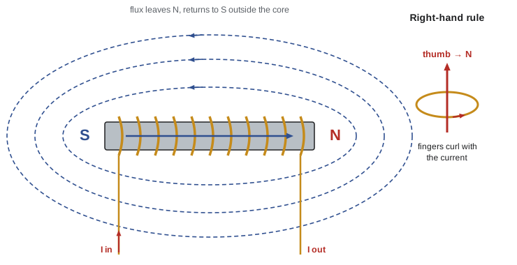
Winding a conductor into a coil concentrates the magnetic field: the fields of all the turns add together inside the coil, which then behaves like a bar magnet with north and south poles. The strength of the field depends on the magnetomotive force, the current multiplied by the number of turns:
measured in ampere-turns. Placing an iron core inside the coil multiplies the flux hundreds or thousands of times, because iron has a much higher permeability than air. The result is an electromagnet: a magnet that can be switched on and off with current. Unlike permanent magnets, electromagnets can be controlled, which is why they appear in so much electrical equipment.
Worked problem
Ampere-turns of a coil
A contactor coil has 2,400 turns and draws 0.05 A when energized from 24 V DC. What is its magnetomotive force and its resistance? If the coil voltage drops to 18 V, what happens to the magnetomotive force?
Show solution
- MMF: \(2400 \times 0.05 = 120\) ampere-turns.
- Resistance: \(24/0.05 = 480\) Ω.
- At 18 V: \(I = 18/480 = 0.0375\) A; MMF \(= 2400 \times 0.0375 = 90\) ampere-turns.
Answer: 120 ampere-turns normally, falling to 90 at 18 V, a 25% reduction in pull. If the voltage drops too low, the contactor may chatter or drop out, which is why control voltage drop (Lesson 11) and undersized control transformers cause trouble.
Uses of electromagnets
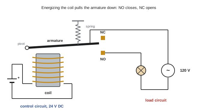
- Relays and contactors: an electromagnet pulls an armature that opens or closes contacts, letting a small control current switch a large load current (ELEC-220 and ELEC-330).
- Solenoids: a plunger pulled into a coil operates valves, door locks and brakes.
- Circuit breakers: a magnetic trip coil carrying the circuit current pulls a latch when a fault produces a high current, opening the breaker almost instantly (Lesson 12).
- Lifting magnets: cranes in scrap yards pick up and release steel.
- Motors and generators: coils create the magnetic fields that produce torque or induce voltage.
- Magnetic locks, bells, buzzers and loudspeakers.
Force on a current in a magnetic field
A conductor carrying current in a magnetic field experiences a force, because its own field interacts with the external field. The force is greatest when the conductor is at right angles to the field:
where \(F\) is the force in newtons, \(B\) the flux density in teslas, \(I\) the current in amperes and \(L\) the length of conductor in the field in metres. The direction is given by Fleming's left-hand rule for motors: with the first finger along the field (north to south), the second finger along the current, the thumb points along the force.
This force is the basis of every electric motor. In a DC motor, current flows through coils on the rotating armature in the field of permanent magnets or field windings; the forces on opposite sides of each coil create a torque that turns the shaft. A commutator, a segmented ring with brushes, reverses the current in each coil at the right moment so the torque always acts in the same direction.
Worked problem
Force on a conductor
A conductor 0.3 m long in a motor carries 50 A at right angles to a field of 0.8 T. What force acts on it? If 40 such conductors act at a radius of 0.1 m, what torque results?
Show solution
- Force per conductor: \(F = 0.8 \times 50 \times 0.3 = 12\) N.
- Total force: \(40 \times 12 = 480\) N; torque \(= 480 \times 0.1 = 48\) N·m.
Answer: 12 N per conductor and 48 N·m in total. Motor torque is therefore proportional to flux and current, which is why a stalled or heavily loaded motor draws high current, and why reducing a motor's field (in some DC drives) changes its speed and torque.
Forces between conductors also matter in power systems. During a short circuit, currents of tens of thousands of amperes produce forces large enough to bend busbars and whip cables, which is why switchgear and cable supports are rated for short-circuit forces and why loose conductors in a panel can be dangerous during a fault.
Electromagnetic induction
In 1831, Michael Faraday discovered the reverse effect: a changing magnetic field around a conductor induces a voltage in it. Faraday's law states that the induced voltage in a coil is proportional to the number of turns and the rate of change of flux:
Lenz's law gives the direction: the induced voltage drives a current that opposes the change that produced it. A voltage can be induced by moving a conductor through a field, moving a magnet near a coil, or changing the current in a nearby coil. For a straight conductor moving at right angles through a field, the induced voltage is \(e = B L v\).
Worked problem
Induced voltage in a coil
A coil of 500 turns sees its flux change from 0 to 0.004 Wb in 0.02 s. What average voltage is induced? What if the change takes 0.002 s?
Show solution
- \(e = 500 \times 0.004/0.02 = 100\) V.
- Ten times faster: \(e = 500 \times 0.004/0.002 = 1{,}000\) V.
Answer: 100 V, rising to 1,000 V if the flux changes ten times faster. The faster the change, the higher the voltage, which explains the high voltage spike when current in a coil is suddenly interrupted (Lesson 10).
Induction is the principle behind:
- Generators: coils rotating in a magnetic field produce AC voltage (Lesson 2).
- Transformers: an alternating current in one coil produces a changing flux in an iron core, inducing a voltage in a second coil; the voltage ratio equals the turns ratio (ELEC-210).
- Induction motors: the changing field of the stator induces currents in the rotor, which then experiences force (ELE-370).
- Current transformers and clamp meters, induction cooktops, wireless chargers and metal detectors.
- Unwanted effects: induced voltages in parallel cables and pipelines, interference, and eddy currents that heat transformer and motor cores (reduced by making cores from thin, insulated laminations).
Magnetic circuits and saturation
Iron can carry only so much flux. As the magnetizing current increases, flux rises steeply at first, then levels off once most of the iron's magnetic domains are aligned: the iron saturates. Beyond saturation, extra current produces little more flux. Motors, transformers and relays are designed to operate below saturation; overvoltage drives them into saturation, causing high magnetizing current and overheating. When iron is magnetized and demagnetized repeatedly (as in AC equipment), some energy is lost in each cycle as hysteresis loss, another reason transformer cores use special low-loss steels.
Common mistakes
MistakeRunning the conductors of one circuit in separate steel raceways.
InsteadKeep all conductors of a circuit together so their fields cancel.
MistakeClamping a meter around both conductors to measure load current.
InsteadClamp one conductor; both together read near zero.
MistakeIgnoring low control voltage at contactor coils.
InsteadCheck coil voltage; low ampere-turns cause chatter and dropout.
MistakeAssuming loose bus or cable supports are harmless.
InsteadShort-circuit forces can move conductors violently.
MistakeApplying overvoltage to magnetic equipment.
InsteadIt saturates cores, raising current and heat.
Summary and key terms
- Magnets have north and south poles; flux is measured in webers, flux density in teslas.
- Current produces a circular magnetic field (right-hand rule); B = μ₀I/(2πr).
- Coils concentrate the field; magnetomotive force = NI; iron cores multiply flux.
- Electromagnets operate relays, contactors, solenoids, breaker trips and motors.
- A current in a field feels a force F = BIL; this drives motors.
- Changing flux induces voltage e = NΔΦ/Δt (Faraday); Lenz's law gives the direction.
- Induction underlies generators, transformers, CTs and induction motors; iron saturates and has losses.
- Magnetic flux
- The total magnetic field through an area, in webers.
- Flux density
- Flux per unit area, in teslas.
- Permeability
- How easily a material carries magnetic flux.
- Right-hand rule
- Thumb along current, fingers curl with the magnetic field.
- Magnetomotive force
- The magnetizing effect of a coil: turns times current.
- Electromagnet
- A coil, usually with an iron core, magnetized by current.
- Relay
- An electromagnetically operated switch.
- Electromagnetic induction
- Production of voltage by a changing magnetic field.
- Lenz's law
- Induced current opposes the change that caused it.
- Saturation
- The point beyond which iron carries little extra flux.
Practice problems
Work each problem on paper first, then reveal the answer to check.
Flux of 0.01 Wb through 0.008 m². Flux density?
Show answer
1.25 T.
Field 0.05 m from a conductor carrying 500 A?
Show answer
2 mT.
Why do the conductors of a circuit run in the same raceway?
Show answer
Their fields cancel, avoiding heating and interference.
Coil of 1,500 turns at 0.2 A. MMF?
Show answer
300 ampere-turns.
How does an iron core affect an electromagnet?
Show answer
It greatly increases the flux.
Conductor 0.2 m, 30 A, 1.2 T. Force?
Show answer
7.2 N.
What does a commutator do in a DC motor?
Show answer
Reverses current in each coil to keep torque in one direction.
200 turns, flux changes 0.01 Wb in 0.05 s. Induced voltage?
Show answer
40 V.
Conductor 0.5 m moving at 10 m/s across 0.4 T. Induced voltage?
Show answer
e = BLv = 2 V.
Why are transformer cores laminated?
Show answer
To reduce eddy current losses.
Lesson quiz · 5 questions
Score 60% or more to complete this lesson.
Create a free account to save your progress, take quizzes and earn a certificate.