
ELEC-110 · Lesson 12 of 12 · 32 min
Overcurrent protection and troubleshooting
This final lesson brings together the theory of the course in two practical skills every electrician uses daily. The first is understanding how circuits are protected from too much current: what fuses and circuit breakers do, how they decide when to open, and why they must be able to interrupt the largest possible fault. The second is troubleshooting: finding out systematically why a circuit does not work, using Ohm's law, Kirchhoff's laws, series and parallel rules, and the meter skills from Lesson 7. Good troubleshooters are not lucky; they follow a method, think about what the circuit should do, and measure to confirm.
Why circuits need overcurrent protection
Every conductor heats up as current flows (\(P = I^2 R\), Lesson 3). Too much current overheats insulation, which softens, cracks and eventually fails, causing fires and further faults. Overcurrent comes in two forms:
- Overload: a current somewhat above the circuit's rating, such as 20 A on a 15 A circuit from too many loads or a jammed motor. It heats conductors gradually, over minutes or hours.
- Short circuit or fault: a very low resistance path between conductors or to ground, causing currents of hundreds or thousands of amperes limited only by the supply and conductor resistance. It can melt metal and cause arcs within milliseconds.
Overcurrent devices, fuses and circuit breakers, open the circuit before damage occurs. They are rated to protect the conductors of the circuit, not the load; motors and equipment often have their own additional protection.
Worked problem
Fault current from Ohm's law
A 120 V circuit is fed from a panel where the source impedance is 0.05 Ω. The branch circuit conductors have a total loop resistance of 0.25 Ω to the point where a short circuit occurs. What fault current flows?
Show solution
- Total resistance: \(0.05 + 0.25 = 0.30\) Ω.
- Fault current: \(120/0.30 = 400\) A.
Answer: 400 A, about 27 times the rating of a 15 A breaker, so it trips almost instantly. If the fault were at the far end of a long circuit with higher loop resistance, the current would be lower and the breaker slower, which is one reason codes limit circuit lengths and require adequate equipment grounding conductors.
Fuses
A fuse contains a metal element that melts when current exceeds its rating for long enough, opening the circuit. Fuses are simple, reliable and fast at high currents, and current-limiting fuses can interrupt a short circuit within the first half-cycle, limiting the energy let through. Types include:
- Standard (non-time-delay) fuses: open quickly on overcurrent; used for resistive loads and electronics.
- Time-delay (dual-element) fuses: tolerate brief inrush currents of motors and transformers but still open quickly on short circuits.
- Current-limiting fuses (such as class J, RK1 and L): very fast on high faults, protecting downstream equipment.
- Semiconductor fuses: extremely fast, to protect drives and power electronics.
A blown fuse must be replaced with the same type and rating, after the cause has been found. Replacing a fuse with a larger one, or bypassing it, removes the protection of the conductors and is a common cause of fires.
Circuit breakers
A circuit breaker is a switch that opens automatically on overcurrent and can be reset. Most low-voltage breakers have two trip elements:
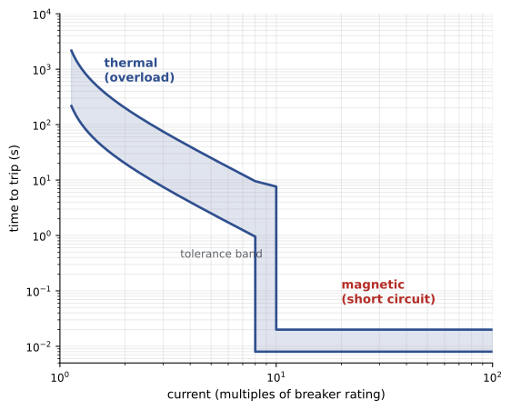
- Thermal: a bimetallic strip heated by the current bends and trips the breaker on sustained overload; the larger the overload, the faster it trips.
- Magnetic: an electromagnet (Lesson 9) pulls the trip latch instantly when current exceeds a high threshold, typically 5 to 10 times the rating for standard breakers, clearing short circuits in a fraction of a second.
Larger breakers use electronic trip units with adjustable settings for long-time, short-time, instantaneous and ground fault protection, used to coordinate protection in commercial and industrial systems (ELEC-220).
Worked problem
Reading a trip curve
A 20 A thermal-magnetic breaker's curve shows: at 30 A (1.5×), trip in 60 s to 300 s; at 100 A (5×), trip in 2 s to 12 s; above 200 A (10×), instantaneous. How does it respond to (a) a 30 A overload, (b) a motor starting at 100 A for 3 s, (c) a 600 A short circuit?
Show solution
- (a) Trips after 1 to 5 minutes.
- (b) Might trip, since 3 s falls within the 2 s to 12 s band; a nuisance trip is possible.
- (c) Trips instantaneously.
Answer: The overload is cleared in minutes, the short circuit instantly, and the motor start may cause nuisance tripping. Motor circuits therefore use breakers or fuses chosen for motor starting, with separate overload relays to protect the motor (ELEC-220).
Interrupting rating
Every fuse and breaker has an interrupting rating (also called interrupting capacity or AIC): the maximum fault current it can safely interrupt. Typical residential breakers are rated 10,000 A; commercial and industrial devices 22,000 A, 65,000 A or more. If the available fault current exceeds the rating, the device may fail to interrupt, exploding and causing an arc flash. Electricians must check that new equipment is rated for the available fault current marked on or calculated for the installation.
Worked problem
Is the breaker adequate?
A panel is fed from a 500 kVA transformer with available fault current at the panel of 14,000 A. The panel's breakers are rated 10,000 A interrupting. Is this acceptable?
Show solution
- Available fault current (14,000 A) exceeds the interrupting rating (10,000 A).
Answer: No. The breakers could fail violently during a fault. Options include using breakers rated 22,000 A or higher, or a tested series-rated combination with an upstream device, as permitted by the code and manufacturer listings.
The Canadian Electrical Code requires overcurrent devices to have interrupting ratings sufficient for the available fault current, and equipment to be marked with its ratings; workplace electrical safety follows CSA Z462.
DC protection
DC circuits need protective devices rated for DC (Lesson 8). DC arcs do not self-extinguish at current zero, so a device rated only for AC may fail to interrupt a DC fault. Battery systems, PV arrays and DC drives use DC-rated fuses and breakers, and their ratings must match the maximum DC voltage, including the higher open-circuit voltage of PV strings in cold weather.
A troubleshooting method
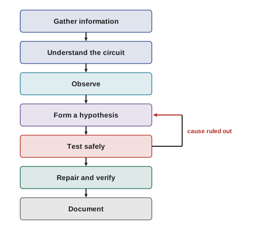
Effective troubleshooting follows a sequence:
1. Gather information: what is the symptom, when did it start, what changed, has it happened before? Talk to the people who use the equipment.
2. Understand how the circuit should work: read the schematic, wiring diagram or ladder diagram, and identify the power source, protective devices, controls and load.
3. Observe: look, listen and smell for obvious signs such as tripped breakers, burnt components, loose wires or overheating.
4. Form a hypothesis: list possible causes consistent with the symptoms.
5. Test: take measurements that will confirm or rule out each cause, starting with the most likely and easiest to check, and always with safe work practices.
6. Repair and verify: fix the root cause, then test the circuit fully under normal operation.
7. Document: record what was found and done.
Finding opens with voltage measurements
In a series circuit, the supply voltage appears across an open (Lesson 5): with no current, there is no voltage drop across the working components, so the full voltage appears across the break. This makes voltage measurements a powerful way to find opens in live circuits, using the half-splitting method: measure at the midpoint of the circuit to determine which half contains the fault, then the midpoint of that half, and so on.
Worked problem
Half-splitting a control circuit
A 24 V DC control circuit has a fuse, a stop button, three limit switches, a start button contact and a relay coil in series. The relay will not energize when start is pressed. With start held, you measure 24 V from the supply negative to each point in turn: after the fuse 24 V, after the stop button 24 V, after the second limit switch 0 V. Where is the fault?
Show solution
- Voltage is present after the stop button, so the fuse and stop button are good.
- Voltage is absent after the second limit switch, so the open is in the first or second limit switch (or the wiring between them).
- Next measurement: after the first limit switch. If 24 V there, the second switch is open; if 0 V, the first is.
Answer: The open is in limit switch 1 or 2; one more measurement isolates it. Half-splitting finds a fault among n points in about log₂ n measurements: for 16 possible points, only 4 measurements are needed.
High-resistance faults and voltage drop testing
Not every fault is a clean open or short. Loose or corroded connections, worn contacts and damaged conductors add resistance that causes heat and low voltage at the load under current, while measuring fine with no load. Voltage drop testing finds them: with the circuit operating, measure the voltage across each connection, switch or conductor section. A good closed switch or connection should show nearly 0 V; a significant reading means resistance there.
Worked problem
A hot connection
A 30 A heater circuit has a connection showing 0.6 V across it under load. What is its resistance and how much heat does it produce?
Show solution
- Resistance: \(0.6/30 = 0.02\) Ω.
- Power: \(0.6 \times 30 = 18\) W.
Answer: 0.02 Ω producing 18 W concentrated in a small connection, enough to discolour insulation and eventually cause failure or fire. Thermal imaging and voltage drop tests under load find such connections before they fail.
Shorts and ground faults
A short or ground fault usually trips the protective device, so the circuit is found dead with a tripped breaker or blown fuse. Resetting a breaker repeatedly onto a fault is dangerous. Instead, with the circuit isolated and locked out, use resistance and insulation resistance measurements (Lesson 7) to find the fault: disconnect loads and sections of the circuit one at a time until the short disappears, half-splitting the circuit as with opens. An insulation resistance tester applies a higher DC voltage (250 V to 1,000 V) to find insulation weaknesses that a normal ohmmeter misses.
Intermittent faults are the hardest: they come and go with temperature, vibration or moisture. Look for patterns (time of day, weather, equipment operation), inspect for chafed cables and water entry, and consider monitoring with a recording meter.
Safety while troubleshooting
Troubleshooting often requires measurements on energized circuits, which is energized electrical work. Electrical safety standards require that it be justified, planned and performed with appropriate controls: a risk assessment, qualified workers, insulated tools, meters with the correct category rating (Lesson 7), personal protective equipment for shock and arc flash, and approach boundaries. Whenever the work can be done de-energized (repairing, changing components, resistance testing), the circuit must be isolated, locked out and verified dead using the live-dead-live method.
In Canada, CSA Z462 and provincial occupational health and safety regulations govern energized work, lockout and personal protective equipment.
Common mistakes
MistakeReplacing a blown fuse with a larger one.
InsteadUse the same type and rating after finding the cause.
MistakeResetting a breaker repeatedly onto a fault.
InsteadIsolate and find the fault before re-energizing.
MistakeInstalling equipment without checking interrupting ratings.
InsteadCompare ratings with the available fault current.
MistakeTesting randomly instead of methodically.
InsteadUnderstand the circuit, form hypotheses and half-split.
MistakeChecking connections only with no load.
InsteadUse voltage drop tests under load to find high resistance.
Summary and key terms
- Overcurrent devices protect conductors from overloads and short circuits.
- Fuses melt; breakers trip thermally on overloads and magnetically on short circuits.
- Time-current curves show how fast devices trip at each current.
- Interrupting ratings must exceed the available fault current; DC needs DC-rated devices.
- A systematic method: gather information, understand, observe, hypothesize, test, repair, document.
- Full voltage appears across an open; half-splitting finds faults quickly.
- Voltage drop tests under load find high-resistance connections; insulation testing finds ground faults.
- Energized troubleshooting needs justification, PPE and safe work practices.
- Overload
- A moderate overcurrent above a circuit's rating.
- Short circuit
- A very low-resistance path causing a very high current.
- Time-delay fuse
- A fuse that tolerates brief inrush but opens on sustained overcurrent or faults.
- Thermal trip
- Breaker tripping by a heated bimetal on sustained overload.
- Magnetic trip
- Instant breaker tripping by an electromagnet on high current.
- Time-current curve
- A graph of trip time versus current for a protective device.
- Interrupting rating
- The maximum fault current a device can safely interrupt.
- Half-splitting
- Testing at midpoints to locate a fault quickly.
- Voltage drop test
- Measuring voltage across components under load to find resistance.
- Intermittent fault
- A fault that comes and goes.
Practice problems
Work each problem on paper first, then reveal the answer to check.
Distinguish an overload from a short circuit.
Show answer
Overload: moderate overcurrent over time; short: very high current through a low-resistance path.
240 V, source 0.04 Ω, circuit loop 0.36 Ω. Fault current?
Show answer
600 A.
Why are time-delay fuses used on motor circuits?
Show answer
They tolerate starting inrush but still clear faults.
Which breaker element handles short circuits?
Show answer
The magnetic trip.
Available fault current 18 kA, breaker rated 10 kA. Acceptable?
Show answer
No.
Why must DC circuits use DC-rated devices?
Show answer
DC arcs do not extinguish at a current zero.
List the steps of the troubleshooting method.
Show answer
Gather information, understand, observe, hypothesize, test, repair and verify, document.
How many half-split measurements to locate a fault among 32 points?
Show answer
5.
A switch shows 1.2 V across it carrying 15 A. Resistance and power?
Show answer
0.08 Ω; 18 W.
What tool finds insulation weaknesses a normal ohmmeter misses?
Show answer
An insulation resistance tester.
Lesson quiz · 5 questions
Score 60% or more to complete this lesson.
Create a free account to save your progress, take quizzes and earn a certificate.