
ELEC-110 · Lesson 10 of 12 · 33 min
Capacitors and inductors in DC circuits
Resistors turn electrical energy into heat. Capacitors and inductors do something different: they store energy, a capacitor in an electric field and an inductor in a magnetic field, and give it back later. This makes them behave in time-dependent ways that resistors do not: a capacitor resists sudden changes in voltage, and an inductor resists sudden changes in current. In DC circuits, these effects show up when a circuit is switched on or off. They explain why drive and power supply capacitors stay dangerously charged after power is removed, why relay coils produce voltage spikes that destroy electronics, how timers and delays work, and why motor starting currents and contact arcing occur. This lesson introduces both components, their time constants and stored energy, and the safety practices they require. ELEC-210 extends them to AC.
Capacitors
A capacitor consists of two conducting plates separated by an insulator called the dielectric. When a voltage is applied, charge flows onto one plate and off the other until the voltage across the capacitor equals the supply. The amount of charge stored per volt is the capacitance, measured in farads (F):
One farad is very large; practical capacitors are rated in microfarads (µF, millionths), nanofarads (nF) and picofarads (pF), although supercapacitors reach thousands of farads at low voltages. Capacitance increases with plate area and dielectric quality and decreases with plate spacing. Every capacitor also has a voltage rating; exceeding it can puncture the dielectric and cause failure, sometimes violently.
Types include ceramic capacitors (small values, electronics), film capacitors (motor run capacitors, power factor correction, drive DC links), electrolytic capacitors (large values in small packages, power supplies and drives, polarized so they must be connected the right way round), and supercapacitors (energy storage for short bursts). Motor start and run capacitors used with single-phase motors are AC capacitors (ELEC-210).
Worked problem
Charge and energy in a capacitor
A drive's DC link has 4,700 µF charged to 680 V. How much charge and energy does it store?
Show solution
- Charge: \(Q = CV = 0.0047 \times 680 = 3.2\) C.
- Energy: \(W = \tfrac{1}{2} C V^2 = 0.5 \times 0.0047 \times 680^2 = 1{,}087\) J.
Answer: About 3.2 C and 1,090 J, enough energy to cause a fatal shock or severe burns from a short circuit. Drives and power supplies warn on their labels to wait a set time, often 5 to 15 minutes, after power is removed and to verify the DC bus is discharged with a meter before touching anything inside.
Charging and discharging: the RC time constant
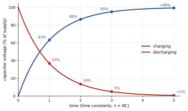
When a capacitor charges through a resistor, the current is largest at first (the empty capacitor offers no opposing voltage) and falls as the capacitor voltage rises. The voltage rises along an exponential curve. The time constant is:
In one time constant, the capacitor charges to about 63% of the supply voltage; after five time constants it is over 99% charged and considered fully charged. Discharging follows the same curve in reverse: after one time constant, 37% of the voltage remains; after five, under 1%.
Worked problem
How long until the bus is safe?
The 4,700 µF DC link above has built-in bleeder resistors totalling 47 kΩ. How long does it take to fall from 680 V to below 50 V?
Show solution
- Time constant: \(\tau = 47{,}000 \times 0.0047 = 221\) s.
- Time: \(t = \tau \ln(680/50) = 221 \times 2.61 = 577\) s, about 9.6 minutes.
Answer: Nearly 10 minutes, which is why the label warns to wait. If a bleeder resistor has failed open, the capacitor can hold a lethal charge for hours, so always measure before touching; never rely on waiting alone.
Worked problem
A time delay
A simple delay circuit charges a 220 µF capacitor through a 100 kΩ resistor from 24 V. A trigger circuit switches when the capacitor reaches 15.2 V. How long is the delay?
Show solution
- \(\tau = 100{,}000 \times 0.00022 = 22\) s.
- 15.2 V is \(15.2/24 = 63\%\) of the supply, which takes one time constant.
Answer: About 22 seconds. Changing the resistor or capacitor adjusts the delay, the principle behind many analog timers. Electrolytic capacitor values vary widely with tolerance and age, so such timers are not precise.
Capacitors in series and parallel
Capacitors combine opposite to resistors. In parallel, the plate areas effectively add, so capacitances add: \(C_T = C_1 + C_2 + \cdots\). In series, the effective spacing increases, so capacitance falls: \(1/C_T = 1/C_1 + 1/C_2 + \cdots\). Capacitors are connected in series to handle higher voltages (with balancing resistors so the voltage divides evenly), as in drive DC links where two banks rated 450 V are connected in series across a 680 V bus.
Worked problem
Combining capacitors
Two 2,200 µF, 450 V capacitors are connected (a) in parallel, (b) in series. What capacitance and voltage rating result?
Show solution
- (a) Parallel: 4,400 µF at 450 V.
- (b) Series: \(1/C = 1/2200 + 1/2200\), so 1,100 µF at up to 900 V (with balancing resistors).
Answer: Parallel doubles capacitance at the same voltage; series halves capacitance and doubles the voltage rating. The stored energy at full rating is the same in both cases.
Inductors
An inductor is a coil of wire, often wound on an iron or ferrite core. When current through it changes, the changing magnetic field induces a voltage that opposes the change (Lesson 9, Lenz's law). Inductance, measured in henries (H), sets how much voltage is induced for a given rate of change of current:
An inductor therefore resists sudden changes in current. With steady DC, the current is constant, no voltage is induced, and the inductor behaves like an ordinary conductor with only its winding resistance. Inductors are found as chokes in drives and power supplies, in relay, contactor and solenoid coils, in motor windings, in ballasts and in filters. Inductance increases with the number of turns squared and with an iron core.
An inductor stores energy in its magnetic field:
The RL time constant
When a DC voltage is applied to an inductor in series with a resistance, the current cannot jump instantly; it rises exponentially toward its final value \(V/R\) with time constant:
After one time constant the current reaches 63% of its final value, and after five it is essentially complete. This delay is why contactors take a few milliseconds to pull in and why large DC motor fields take time to build up.
Worked problem
Current rise in a coil
A DC brake coil has an inductance of 2 H and a resistance of 40 Ω, supplied at 120 V. What is the final current, the time constant and the current after 50 ms?
Show solution
- Final current: \(120/40 = 3\) A.
- Time constant: \(\tau = 2/40 = 0.05\) s = 50 ms.
- After one time constant: \(0.63 \times 3 = 1.9\) A.
Answer: 3 A final, a 50 ms time constant, and about 1.9 A after 50 ms; the coil reaches full current in about 250 ms. The brake engages accordingly, which matters for timing on hoists and conveyors.
Inductive kick: switching off a coil
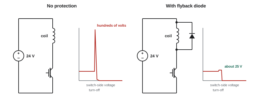
Interrupting the current in an inductor is the dangerous part. The current tries to keep flowing, and because \(v = L\, \Delta i/\Delta t\), a very fast interruption induces a very high voltage, often hundreds or thousands of volts from a 24 V coil. This "inductive kick" causes arcing across switch contacts, erodes relay contacts, destroys transistors and PLC outputs, and can give a nasty shock when disconnecting a coil or a motor field.
Worked problem
Size of the kick
A relay coil with 0.5 H carries 0.1 A. A switch interrupts the current in 10 µs. Estimate the induced voltage.
Show solution
- \(v = L\, \Delta i/\Delta t = 0.5 \times 0.1/0.00001 = 5{,}000\) V.
Answer: About 5,000 V in theory; in practice an arc forms across the contacts or something breaks down at a lower voltage, but it is far above the 24 V supply. The energy stored, \(\tfrac{1}{2} \times 0.5 \times 0.1^2 = 2.5\) mJ, is small, yet enough to damage electronics.
The standard remedies give the coil current somewhere to go when it is switched off:
- Flyback (freewheeling) diode across DC coils, connected so it does not conduct normally but carries the coil's current when the switch opens, limiting the spike to about 1 V. It slows the coil's release slightly.
- Resistor-capacitor (RC) snubbers or metal oxide varistors across AC or DC coils.
- Transient voltage suppression diodes for faster release with limited spike.
Many relays and contactors are available with suppression modules built in, and PLC manufacturers specify suppression for inductive loads on their outputs (ELEC-330).
Capacitors and inductors compared
| Property | Capacitor | Inductor |
|---|---|---|
| Stores energy in | Electric field | Magnetic field |
| Opposes sudden changes in | Voltage | Current |
| With steady DC, behaves like | An open circuit (after charging) | A short circuit (only winding resistance) |
| Time constant | τ = RC | τ = L/R |
| Energy | ½CV² | ½LI² |
| Hazard | Stays charged after power is removed | High-voltage spike when current is interrupted |
| Unit | Farad (F) | Henry (H) |
Safe work with stored energy
Stored electrical energy is a recognized hazard in electrical safety standards. Before working on equipment with capacitors, such as drives, UPS systems, power supplies, power factor correction banks and medium-voltage equipment:
- Isolate and lock out the supply.
- Wait the time marked by the manufacturer.
- Verify the absence of voltage with a properly rated meter, measuring across the DC bus or capacitor terminals as well as the input terminals.
- Discharge capacitors through an appropriate resistor tool if required; never short them with a screwdriver.
- For high-voltage capacitor banks, apply grounding and shorting devices before contact.
CSA Z462 requires stored energy to be considered in the electrical risk assessment and in establishing an electrically safe work condition.
Common mistakes
MistakeAssuming a drive is safe as soon as it is switched off.
InsteadWait the marked time and verify the DC bus voltage with a meter.
MistakeShorting a charged capacitor with a screwdriver.
InsteadDischarge through a proper resistor tool.
MistakeConnecting an electrolytic capacitor backwards.
InsteadObserve polarity; reversed electrolytics can burst.
MistakeSwitching DC coils from transistor outputs without suppression.
InsteadFit a flyback diode or suppressor.
MistakeUsing the resistor combination rules for capacitors.
InsteadCapacitors add in parallel and combine reciprocally in series.
Summary and key terms
- Capacitors store charge Q = CV and energy ½CV²; they resist sudden voltage changes.
- RC circuits charge to 63% in one time constant τ = RC and are complete in five.
- Capacitances add in parallel and combine reciprocally in series.
- Inductors resist sudden current changes: v = L Δi/Δt; energy ½LI².
- RL circuits rise with time constant τ = L/R.
- Interrupting inductor current causes a high-voltage kick; flyback diodes and snubbers control it.
- Stored energy must be isolated, allowed to dissipate and verified before work.
- Capacitance
- Charge stored per volt, in farads.
- Dielectric
- The insulator between a capacitor's plates.
- Electrolytic capacitor
- A polarized capacitor with high capacitance per volume.
- Time constant
- The time for a charging quantity to reach 63% of its final change.
- Bleeder resistor
- A resistor that discharges a capacitor after power is removed.
- Inductance
- Voltage induced per rate of change of current, in henries.
- Choke
- An inductor used to limit or smooth current.
- Inductive kick
- A high-voltage spike when inductor current is interrupted.
- Flyback diode
- A diode across a DC coil that clamps switching spikes.
- Snubber
- A circuit, often RC, that suppresses switching transients.
Practice problems
Work each problem on paper first, then reveal the answer to check.
Charge on 100 µF at 50 V?
Show answer
5 mC.
Energy in 1,000 µF at 400 V?
Show answer
80 J.
Time constant of 10 kΩ and 470 µF?
Show answer
4.7 s.
A 12 V source charges an RC circuit. Voltage after one and three time constants?
Show answer
7.6 V; 11.4 V.
Capacitors of 10, 22 and 47 µF in parallel?
Show answer
79 µF.
Two 100 µF in series?
Show answer
50 µF.
Inductor of 0.2 H, current change 2 A in 0.01 s. Induced voltage?
Show answer
40 V.
Time constant of 4 H and 80 Ω?
Show answer
50 ms.
Energy in 0.1 H carrying 5 A?
Show answer
1.25 J.
What does a flyback diode do?
Show answer
Gives coil current a path at switch-off, clamping the voltage spike.
Lesson quiz · 5 questions
Score 60% or more to complete this lesson.
Create a free account to save your progress, take quizzes and earn a certificate.