
ELEC-110 · Lesson 6 of 12 · 35 min
Circuit analysis techniques
Lesson 5 covered the rules for series, parallel and combination circuits and Kirchhoff's laws. Many practical circuits need a few more tools: dividers that are loaded by what they feed, bridges that measure small changes in resistance, sources that have their own internal resistance, circuits with more than one source, and three-wire systems with a shared neutral. This lesson develops these tools at the level an electrician needs to understand control circuits, sensors, batteries and the split-phase systems found in every home. The same ideas reappear in AC circuits (ELEC-210) and in engineering courses (ELE-202).
Voltage dividers under load
An unloaded voltage divider of two series resistors \(R_1\) and \(R_2\) across a supply \(V_s\) gives an output across \(R_2\) of:
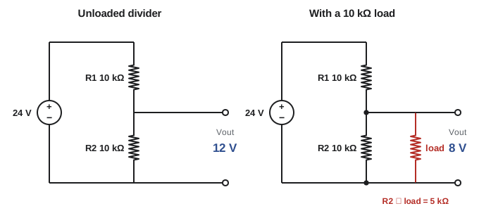
When a load \(R_L\) is connected across the output, it is in parallel with \(R_2\), lowering the effective resistance of the lower leg and therefore the output voltage. The divider only holds its unloaded value if the load resistance is much larger than \(R_2\), typically at least ten times larger.
Worked problem
A loaded divider
A divider uses \(R_1 = 10\) kΩ and \(R_2 = 10\) kΩ across 24 V. What is the output unloaded? With a 100 kΩ load? With a 10 kΩ load?
Show solution
- Unloaded: \(24 \times 10/20 = 12\) V.
- 100 kΩ load: \(R_2 \parallel R_L = 10 \times 100/110 = 9.09\) kΩ; \(V_{out} = 24 \times 9.09/19.09 = 11.4\) V.
- 10 kΩ load: \(R_2 \parallel R_L = 5\) kΩ; \(V_{out} = 24 \times 5/15 = 8.0\) V.
Answer: 12 V unloaded, 11.4 V with a 100 kΩ load and only 8.0 V with a 10 kΩ load. This is why dividers are used only to feed high-resistance inputs such as controller analog inputs, and why a meter with low input resistance can upset a reading (Lesson 7).
Current dividers
In a parallel circuit, current divides so that branches with lower resistance carry more current. For two branches, the current in branch 1 is:
Note that the other branch's resistance appears on top: the smaller \(R_1\) is, the larger its share. Current dividers explain how shunts work in ammeters, how parallel conductors share current (and why unequal lengths cause unequal sharing), and how ground fault current divides between paths.
Worked problem
Parallel conductors sharing current
Two parallel conductors carry a total of 400 A. Because one is slightly longer, their resistances are 0.010 Ω and 0.012 Ω. How is the current shared?
Show solution
- Shorter conductor: \(I_1 = 400 \times 0.012/0.022 = 218\) A.
- Longer conductor: \(I_2 = 400 \times 0.010/0.022 = 182\) A.
Answer: 218 A and 182 A instead of 200 A each. The shorter conductor carries 9% more than its share and could overheat if sized exactly for 200 A. This is why codes require parallel conductors to be the same length, material, size and termination (ELEC-120).
Bridge circuits
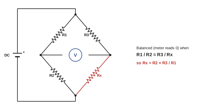
A Wheatstone bridge consists of two voltage dividers side by side across the same supply, with a meter connected between their midpoints. When the ratios of the two dividers are equal, the midpoints are at the same voltage and the meter reads zero: the bridge is balanced.
Bridges detect very small changes in resistance, so they are used with strain gauges in load cells and pressure transmitters, with RTDs in temperature measurement, and in older precision resistance meters. A small change in one resistor unbalances the bridge and produces a small voltage proportional to the change.
Worked problem
Finding an unknown resistance
A bridge balances with \(R_1 = 1{,}000\) Ω, \(R_2 = 1{,}000\) Ω and \(R_3 = 138.5\) Ω. What is \(R_x\)? If \(R_x\) is a Pt100 RTD (100 Ω at 0 °C, 0.385 Ω/°C), what temperature is it?
Show solution
- \(R_x = 138.5 \times 1000/1000 = 138.5\) Ω.
- Temperature: \((138.5 - 100)/0.385 = 100\) °C.
Answer: 138.5 Ω, corresponding to 100 °C. Temperature transmitters use bridges like this internally and convert the result to a 4–20 mA signal (ELEC-330).
Sources with internal resistance
Real sources are not ideal. A battery, generator or power supply behaves like an ideal voltage source in series with a small internal resistance \(r\). When current flows, some voltage is dropped inside the source, so the terminal voltage falls as load increases:
where \(E\) is the open-circuit voltage (sometimes called the electromotive force). Internal resistance explains why a weak battery shows nearly full voltage on a meter but collapses when a load is connected, why cranking a cold engine drops a car battery's voltage, and why a short circuit on a battery produces a large but limited current.
Worked problem
Load testing a battery
A 12 V battery reads 12.6 V with no load and 11.4 V while supplying 120 A to a load tester. What is its internal resistance? What current would flow into a short circuit?
Show solution
- \(r = (12.6 - 11.4)/120 = 0.010\) Ω.
- Short-circuit current: \(I = E/r = 12.6/0.010 = 1{,}260\) A.
Answer: About 10 mΩ internal resistance and over 1,200 A into a short circuit, enough to weld tools and cause severe burns or battery explosions. Internal resistance rises as batteries age, which is why load tests and impedance tests reveal weak batteries that a simple voltage reading misses (Lesson 8).
Maximum power transfer
A source delivers the most power to a load when the load resistance equals the source's internal resistance. At that point, however, half the power is wasted inside the source, so efficiency is only 50%. Power systems never operate this way; they keep the load resistance much higher than the source resistance for high efficiency. Matching matters in communications and audio, where getting the most signal power is more important than efficiency.
Worked problem
Matching and efficiency
A source of 10 V with 2 Ω internal resistance supplies a load. Find the load power and efficiency for load resistances of 2 Ω and 18 Ω.
Show solution
- 2 Ω: \(I = 10/4 = 2.5\) A; load power \(2.5^2 \times 2 = 12.5\) W; efficiency 50%.
- 18 Ω: \(I = 10/20 = 0.5\) A; load power \(0.5^2 \times 18 = 4.5\) W; efficiency 90%.
Answer: The matched load gets more power (12.5 W) but at 50% efficiency; the 18 Ω load gets less power but at 90% efficiency. Power distribution aims for efficiency, so internal and conductor resistances are kept small compared with loads.
Circuits with more than one source
When a circuit has two or more sources, such as batteries in parallel or a battery being charged by a charger, Kirchhoff's laws (Lesson 5) still apply. One useful method is superposition: in a circuit of resistors, the current in any branch equals the sum of the currents caused by each source acting alone, with the other voltage sources replaced by short circuits (and current sources by open circuits).
Worked problem
Two batteries in parallel
Two batteries are connected in parallel to share a 1 Ω load. Battery A has \(E = 12.6\) V and \(r = 0.05\) Ω; battery B is weaker, with \(E = 12.2\) V and \(r = 0.05\) Ω. Find the load voltage and each battery's current.
Show solution
- Let the load voltage be \(V\). Battery currents: \(I_A = (12.6 - V)/0.05\), \(I_B = (12.2 - V)/0.05\). Load current \(V/1\).
- KCL: \((12.6 - V)/0.05 + (12.2 - V)/0.05 = V\) gives \(20(24.8 - 2V) = V\), so \(496 = 41V\) and \(V = 12.10\) V.
- \(I_A = (12.6 - 12.10)/0.05 = 10.0\) A; \(I_B = (12.2 - 12.10)/0.05 = 2.0\) A; load current 12.1 A.
Answer: The load sees 12.1 V; the strong battery supplies 10 A and the weak one only 2 A. With no load, current would circulate from the strong battery into the weak one, \((12.6 - 12.2)/0.1 = 4\) A. This is why batteries connected in parallel should be of the same type, age and state of charge.
Three-wire systems and the neutral
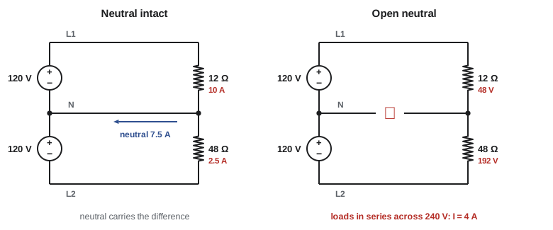
Homes in North America are supplied by a three-wire system: two "hot" conductors and a neutral, giving 120 V from each hot to neutral and 240 V between the hots. The same idea in DC, the Edison three-wire system, was used in the first distribution networks. With loads on each side, the neutral carries only the difference between the two side currents:
When the two sides are balanced, the neutral carries no current. If the neutral is broken (an "open neutral"), the two 120 V loads end up in series across 240 V, and the voltage divides according to their resistances: the side with the lighter load (higher resistance) gets more than 120 V and can be damaged.
Worked problem
An open neutral
On a 120/240 V system, side 1 has a 1,200 W load and side 2 a 300 W load (both rated at 120 V). Find the neutral current when everything is connected, and the voltage across each load if the neutral opens.
Show solution
- Normal: \(I_1 = 10\) A, \(I_2 = 2.5\) A, neutral current \(10 - 2.5 = 7.5\) A.
- Resistances: \(R_1 = 120^2/1200 = 12\) Ω; \(R_2 = 120^2/300 = 48\) Ω.
- Open neutral: in series across 240 V, \(I = 240/60 = 4\) A; \(V_1 = 4 \times 12 = 48\) V; \(V_2 = 4 \times 48 = 192\) V.
Answer: Normally the neutral carries 7.5 A. With an open neutral, the large load drops to 48 V while the small load is driven to 192 V, likely destroying it. Lights that brighten and dim as loads switch on are a classic sign of a loose or open neutral, which should be treated as an urgent hazard.
Solving circuits systematically
For any DC circuit, a reliable approach is:
1. Draw the circuit neatly and label every component, source and node.
2. Simplify series and parallel groups where possible (Lesson 5).
3. For circuits that cannot be simplified, write Kirchhoff's current law at nodes or voltage law around loops, and solve the equations.
4. Check the answer: currents into each node should sum to zero, voltages around each loop should sum to zero, and total power supplied should equal total power used.
5. Ask whether the result makes sense physically.
Engineering courses (ELE-202) formalize these methods as nodal and mesh analysis and add theorems such as Thévenin's, which replaces any network seen from two terminals by a single source and series resistance, exactly the model of a source with internal resistance used above.
Common mistakes
MistakeUsing the unloaded divider formula when a load is connected.
InsteadCombine the load in parallel with the lower resistor.
MistakePutting the branch's own resistance on top in the current divider formula.
InsteadThe other branch's resistance goes on top.
MistakeJudging a battery by its open-circuit voltage alone.
InsteadLoad test or measure internal resistance.
MistakeParalleling batteries of different ages or charge.
InsteadMatch type, age and state of charge to avoid circulating current.
MistakeIgnoring flickering lights that brighten and dim.
InsteadSuspect a loose or open neutral and investigate immediately.
Summary and key terms
- A loaded divider's output falls because the load parallels the lower resistor; keep loads at least 10× R₂.
- Current divides inversely with resistance: I₁ = I_T R₂/(R₁ + R₂).
- Unequal parallel conductors share current unequally.
- A Wheatstone bridge balances when R₁/R₂ = R₃/R_x; it measures small resistance changes.
- Real sources have internal resistance: V = E − Ir; short-circuit current = E/r.
- Maximum power transfer occurs at a matched load but at only 50% efficiency.
- In three-wire systems the neutral carries the imbalance; an open neutral can overvoltage the lighter side.
- Loaded divider
- A voltage divider with a load connected to its output.
- Current divider
- Parallel branches that share a total current.
- Wheatstone bridge
- Two dividers side by side used to measure resistance.
- Balanced bridge
- A bridge with zero voltage between its midpoints.
- Internal resistance
- The resistance inside a source that lowers terminal voltage under load.
- Electromotive force (EMF)
- The open-circuit voltage of a source.
- Maximum power transfer
- Load resistance equal to source resistance gives maximum load power.
- Superposition
- Summing the effects of each source acting alone.
- Three-wire system
- A supply with two hot conductors and a shared neutral.
- Open neutral
- A broken neutral conductor causing unbalanced voltages.
Practice problems
Work each problem on paper first, then reveal the answer to check.
Divider 20 kΩ over 5 kΩ across 15 V. Unloaded output?
Show answer
3 V.
Same divider with a 5 kΩ load. Output?
Show answer
R₂‖R_L = 2.5 kΩ; 15 × 2.5/22.5 = 1.67 V.
30 A splits between 4 Ω and 6 Ω. Current in the 4 Ω branch?
Show answer
30 × 6/10 = 18 A.
Bridge balances with R₁ = 500, R₂ = 1,000, R₃ = 60 Ω. R_x?
Show answer
120 Ω.
Battery 6.3 V open circuit, 5.9 V at 20 A. Internal resistance?
Show answer
0.02 Ω.
Short-circuit current of that battery?
Show answer
315 A.
Source 24 V with 4 Ω internal resistance. Load for maximum power, and that power?
Show answer
4 Ω; 36 W.
Side loads of 15 A and 9 A on a 120/240 V system. Neutral current?
Show answer
6 A.
Open neutral with 24 Ω and 72 Ω loads across 240 V. Voltages?
Show answer
60 V and 180 V.
What symptom suggests an open neutral?
Show answer
Lights brightening and dimming as other loads switch.
Lesson quiz · 5 questions
Score 60% or more to complete this lesson.
Create a free account to save your progress, take quizzes and earn a certificate.