
ELEC-110 · Lesson 7 of 12 · 36 min
Meters and measurement
An electrician's meter is a safety tool first and a measuring tool second. The same multimeter that tells you a circuit carries 118 V is the tool that proves a circuit is dead before you touch it, and a meter used wrongly, set to the wrong function, connected the wrong way or rated for the wrong environment, can explode in your hands. This chapter covers the instruments you will use every day, how to connect them, how to read their accuracy, how meters can fool you, and the measurement category ratings that decide where a meter can be used safely.
The digital multimeter
A digital multimeter (DMM) combines a voltmeter, an ammeter and an ohmmeter, and usually adds continuity, diode, capacitance and frequency functions. Most electricians' meters are "true-RMS", meaning they read the effective value of AC correctly even when the waveform is distorted, as it often is with electronic loads.
A DMM has a rotary function switch and usually three or four jacks: COM (common, the black lead), V/Ω (red lead for volts, ohms and continuity), and A or mA (red lead for current). The single most common way to destroy a meter, or start an arc flash, is to leave the red lead in the A jack and then touch the probes across a voltage.
Measuring voltage
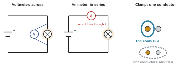
A voltmeter is connected in parallel with (across) the component or between the two points whose potential difference you want. It has a very high internal resistance, typically 10 MΩ for a DMM, so it draws almost no current and barely disturbs the circuit.
On AC circuits, typical readings in North America are about 120 V line to neutral and 240 V line to line in a home, 120 V and 208 V in a 120/208 V building, and higher on commercial systems. Readings within roughly 5% of nominal are normal; much lower readings under load suggest loose connections, undersized conductors or an overloaded supply (Lesson 11).
Measuring current
An ammeter must be connected in series so that the current passes through it, which means opening the circuit. Its internal resistance is very low, a small fraction of an ohm, so it does not reduce the current it measures.
Worked problem
Why an ammeter across a supply is dangerous
An apprentice leaves the leads in the 10 A jacks and touches them across a 120 V receptacle. If the meter's current path has a resistance of 0.01 Ω, what current would flow if nothing else limited it?
Show solution
- \(I = V/R = 120/0.01 = 12\,000\) A.
Answer: Thousands of amperes: in practice the wiring limits it to hundreds or thousands, the meter's internal fuse blows, and if the fuse is not a proper high-energy type, the meter can explode or start an arc. Never connect the current jacks across a voltage, and check the jacks before every voltage test
Clamp meters
Opening a circuit to measure current is slow and often unsafe, so electricians normally use a clamp meter (clamp-on ammeter). Its jaws surround one conductor and sense the magnetic field produced by the current, without any electrical contact. Clamp meters measure AC easily; models with a Hall-effect sensor also measure DC.
Worked problem
The cord that reads zero
An electrician clamps around a whole appliance cord, containing both the line and neutral conductors, while a 10 A heater runs. The clamp reads about 0 A. Why?
Show solution
- The line conductor carries 10 A toward the heater and the neutral carries 10 A back.
- Their magnetic fields are equal and opposite, so they cancel inside the jaws.
Answer: The currents cancel. Clamp around one conductor only, or use a line splitter accessory. (A small reading when clamping both conductors means some current is returning by another path, which is how leakage clamps find ground faults)
Measuring resistance and continuity
An ohmmeter passes a small current from its own battery through the component and measures the resulting voltage. Because it supplies its own current, it must only be used on de-energized, isolated components. Measuring resistance on a live circuit gives wrong readings and can damage the meter.
A continuity test is a quick resistance check that beeps when the resistance is low (a few ohms or less), used to check fuses, switches, conductors and connections. Always disconnect at least one end of the component, or the meter may measure a parallel path through other parts of the circuit.
Worked problem
Checking a heater element
A 240 V, 3000 W baseboard heater is removed from service and isolated. What resistance should the element measure if it is good? What reading would indicate it is open, or shorted?
Show solution
- Expected operating resistance: \(R = V^2/P = 240^2/3000 = 19.2\) Ω. Cold, it will read slightly less, since nickel–chromium heater wire changes resistance only a little with temperature.
- An open element reads OL (over-limit, infinite resistance).
- A shorted element reads far below 19 Ω, near 0 Ω.
Answer: About 19 Ω when good, OL when open, near 0 Ω when shorted. Also check from each terminal to the heater's metal frame: it should read OL, or a ground fault exists
Insulation resistance testing
An ordinary ohmmeter uses only a few volts, too little to reveal weak insulation. An insulation resistance tester (often called a megger, after a well-known brand) applies a DC test voltage such as 500 V or 1000 V between conductors, or between a conductor and ground, and reads resistance in megohms. Good insulation reads hundreds or thousands of megohms; a low reading means damaged, wet or contaminated insulation. Before testing, the circuit must be de-energized, and loads and electronic equipment that the test voltage could damage must be disconnected.
Accuracy and resolution
No meter is perfect. Manufacturers state accuracy as a percentage of the reading plus a number of counts (digits) in the last place shown.
Worked problem
How accurate is the reading?
A DMM on its 600.0 V range reads 240.0 V. Its AC voltage specification is ±(1.0% + 3 counts). What range could the true voltage lie in?
Show solution
- 1.0% of 240.0 V = 2.4 V.
- On the 600.0 V range the last digit is 0.1 V, so 3 counts = 0.3 V.
- Total uncertainty = ±(2.4 + 0.3) = ±2.7 V.
Answer: Between 237.3 V and 242.7 V. For most troubleshooting that is plenty; for calibration or tight specifications, use a more accurate instrument and read its datasheet
Resolution is the smallest change the display can show (0.1 V on a 600.0 V range); accuracy is how close the reading is to the truth. A display showing many digits is not necessarily accurate.
How meters can fool you
Meter loading
A 10 MΩ voltmeter barely affects most power circuits, but in high-resistance electronic circuits it can change the very voltage it measures.
Worked problem
A voltmeter that changes the circuit
Two 1 MΩ resistors in series form a divider across 24 V, so the middle point should be at 12 V. What does a DMM with 10 MΩ input resistance read across the lower resistor?
Show solution
- The meter is in parallel with the lower 1 MΩ: \(R_P = (1 \times 10)/(1 + 10) = 0.909\) MΩ.
- Divider: \(V = 24 \times 0.909/(1 + 0.909) = 11.43\) V.
Answer: About 11.4 V instead of 12 V, an error of nearly 5% caused by the meter itself. On power circuits with low resistances the effect is negligible
Ghost voltage
A high-impedance meter can show a voltage, sometimes tens of volts, on a conductor that is disconnected from the supply but runs alongside energized conductors. Capacitive coupling between the wires produces the reading, but it cannot deliver real current. Many electricians' meters have a low-impedance (LoZ) mode that loads the circuit enough to make ghost voltages collapse while a real supply still reads correctly. Never assume a reading is a ghost voltage; prove it.
Non-contact voltage testers
Pen-style non-contact voltage testers light up near energized AC conductors. They are convenient for a first check but can miss voltage (shielded cable, DC, a dead battery, a conductor deep in a box) and can light up on ghost voltages. They are never sufficient on their own to prove a circuit is de-energized.
Measurement categories (CAT ratings)
When a meter is connected to a circuit, a transient voltage spike, from lightning, switching or a fault, can reach the meter. The closer you are to the utility supply, the more energy such a transient can carry. The international meter safety standard IEC 61010-1 (adopted in Canada as CSA C22.2 No. 61010-1 and in the United States as UL 61010-1) defines measurement categories:
- CAT II: circuits connected to receptacles: appliances, portable tools.
- CAT III: building distribution: panels, feeders, branch circuit wiring, fixed equipment such as motors and lighting.
- CAT IV: the origin of the installation: the utility service, meter base, service entrance conductors and outdoor overhead or underground lines.
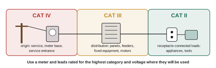
A meter is rated by category and voltage, for example "CAT III 1000 V, CAT IV 600 V". Use a meter only where both ratings meet or exceed the circuit. Check that the test leads carry matching ratings too, and look for the mark of an accredited testing laboratory; inexpensive meters with unverifiable ratings have failed violently in real arc flash incidents.
Proving a circuit dead: live–dead–live
Before working on any circuit, you must establish an electrically safe work condition: identify the sources, open the disconnects, lock and tag them out, and then test to prove there is no voltage. CSA Z462, Workplace Electrical Safety, and provincial occupational health and safety regulations set out the requirements. The test itself follows the live–dead–live method:
- Live: test your meter on a known energized source of similar voltage to prove it works.
- Dead: test the circuit you will work on, phase to phase and each phase to ground (and to neutral), to prove it is de-energized.
- Live: test the meter again on the known source to prove it did not fail during the test.
Use a meter rated for the circuit, wear the PPE your employer's procedures require until the absence of voltage is proven, and treat the circuit as live until all three steps pass. Course ELEC-420 and the safety stream course HSE-224 go further into energized work and arc flash.
Worked problem
Is it safe to start?
An electrician locks out a 240 V circuit, tests it with a meter and gets 0 V on both legs to ground and between legs, then starts work. Later the meter is found to have a blown fuse in its voltage circuit. What step was missed?
Show solution
- A meter with a failed input reads 0 V everywhere, live or dead.
- Testing on a known live source before and after the test would have revealed the faulty meter.
Answer: The "live" checks of live–dead–live were skipped. A dead reading means nothing unless the meter is proven to work immediately before and after
Common mistakes
MistakeMeasuring voltage with the red lead still in the A jack.
InsteadCheck the jacks and function every time; the current jacks are a near short circuit.
MistakeConnecting an ammeter in parallel or using an ohmmeter on a live circuit.
InsteadAmmeters go in series (or use a clamp); ohmmeters only on de-energized, isolated parts.
MistakeClamping around a whole cable.
InsteadClamp one conductor; outgoing and return currents cancel.
MistakeRelying on a non-contact tester to prove a circuit dead.
InsteadUse a rated contact tester with the live–dead–live method.
MistakeUsing a CAT II meter in a panel or at a service.
InsteadMatch the meter's category and voltage to the location: CAT III for panels and feeders, CAT IV at the service.
Summary and key terms
- A DMM measures voltage, current and resistance; check the function and jacks before every test.
- Voltmeters connect in parallel (high resistance, about 10 MΩ); ammeters connect in series (very low resistance); clamp meters surround one conductor.
- Ohmmeters and continuity testers are used only on de-energized, isolated components; insulation testers apply hundreds of volts DC and read megohms.
- Accuracy = ±(% of reading + counts); resolution is not accuracy.
- Meter loading, ghost voltages and non-contact testers can mislead; LoZ mode helps distinguish ghost voltages.
- CAT II (receptacle loads), CAT III (distribution), CAT IV (service origin): use a meter and leads rated for the location and voltage.
- Prove circuits dead with live–dead–live, after lockout, using a rated meter.
- Digital multimeter (DMM)
- A meter combining voltage, current and resistance functions.
- True RMS
- A meter that reads the effective value of AC correctly even for distorted waveforms.
- Clamp meter
- A meter that measures current by sensing the magnetic field around a conductor.
- Continuity
- An unbroken, low-resistance path.
- OL
- Over-limit: the meter reading for a resistance too high to measure, such as an open circuit.
- Insulation resistance tester
- An instrument that applies a high DC voltage to measure insulation resistance in megohms.
- Meter loading
- The change in a circuit caused by connecting a meter to it.
- Ghost voltage
- A reading on a disconnected conductor caused by capacitive coupling to nearby energized conductors.
- Measurement category (CAT)
- A rating of the transient overvoltage a meter can withstand at locations in an electrical system.
- Live–dead–live
- Testing a meter on a known live source, testing the circuit, then retesting the meter.
Practice problems
Work each problem on paper first, then reveal the answer to check.
How is a voltmeter connected to measure the voltage across a motor? An ammeter to measure its current?
Show answer
Voltmeter across (in parallel with) the motor terminals; ammeter in series with one supply conductor, or a clamp meter around one conductor.
Why does a voltmeter have a high internal resistance and an ammeter a low one?
Show answer
So that each disturbs the circuit as little as possible: the voltmeter draws almost no current; the ammeter adds almost no resistance.
A meter on its 60.00 V range reads 24.00 V with an accuracy of ±(0.5% + 2 counts). Find the possible range of the true value.
Show answer
0.5% of 24 = 0.12 V; 2 counts = 0.02 V; ±0.14 V: 23.86 V to 24.14 V.
A 240 V, 4000 W element is isolated. What resistance should a good element read?
Show answer
240²/4000 = 14.4 Ω (a little less cold).
A disconnected conductor reads 38 V on a high-impedance meter but 0 V in LoZ mode. What is the likely explanation?
Show answer
A ghost voltage from capacitive coupling to nearby energized conductors.
Which measurement category applies at a residential meter base? At a branch-circuit receptacle? Inside a distribution panel?
Show answer
CAT IV at the meter base; CAT II at the receptacle; CAT III in the panel.
A meter is rated CAT III 600 V. May it be used on a 480 V motor control centre? At a 600 V service entrance?
Show answer
Yes for the 480 V MCC (CAT III, under 600 V). No at the service entrance, which needs a CAT IV rating.
List the three steps of live–dead–live.
Show answer
Test the meter on a known live source; test the circuit to prove it dead; retest the meter on the known live source.
Why should one end of a component be disconnected before measuring its resistance?
Show answer
Otherwise the meter may read a parallel path through other parts of the circuit.
A clamp around both conductors of a cord to a running appliance reads 0.4 A. What might this indicate?
Show answer
Some current is returning by another path, such as leakage to ground: a possible ground fault.
Lesson quiz · 5 questions
Score 60% or more to complete this lesson.
Create a free account to save your progress, take quizzes and earn a certificate.