
DCE-320 · Lesson 8 of 12 · 32 min
Pathways, cable trays and fill
Every cable in a data centre needs a route: a pathway that supports it, protects it, keeps it away from things that would damage or interfere with it, and leaves room for the cables that will be added later. Pathways are also a large part of the coordination problem in a data hall. Cable trays share the ceiling space with power busway, lighting, fire sprinkler pipes, containment structures and sometimes liquid cooling pipework, and each has its own clearances. A pathway plan drawn early, with heights and routes for each system, saves expensive conflicts during construction.
This lesson covers the types of pathway, how to lay them out in a hall, how to calculate fill and weight, bend radius and pulling limits, separation from power, fire ratings of cables, firestopping, and the bonding of pathways and cabinets.
Types of pathway
- Ladder rack: two side rails joined by rungs, usually steel, supporting heavy cable bundles. Common in network rooms and above rows in older designs.
- Wire mesh (basket) tray: a light welded-wire tray that can be cut and bent on site for drops and changes of direction. The most common pathway above cabinet rows in modern halls.
- Solid-bottom and ventilated trays: used where cables need more protection or support, such as in risers.
- Fibre raceway: plastic duct systems (often yellow) with smooth, controlled-radius fittings, made for patch cords and small fibre cables that would be crushed or bent too tightly in wire tray.
- Conduit: enclosed metal or PVC raceway for routes through walls, between buildings, in areas needing physical protection, and wherever the code or building design requires it.
- Under-floor pathways: trays or baskets under a raised access floor. Once standard, they are now used less for cabling, because cables under the floor block the cooling air that the floor plenum carries, are hard to trace, and accumulate abandoned cable. Many raised-floor halls run power under the floor and data overhead, or put everything overhead.
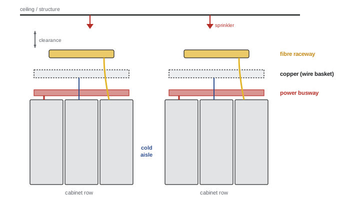
TIA-942 recommends that overhead pathways be arranged in layers by system, for example power at one level, copper data above or below it and fibre raceway at another, so that each can be accessed and expanded without disturbing the others, and so that power and data cross at right angles where they must cross.
Laying out pathways
A good pathway layout follows a few principles:
- Follow the rows. The main pathways run along the rows, above the cabinets, with cross-aisle pathways connecting them to the HDA and MDA. Drops into each cabinet come from directly above.
- Keep the hot and cold aisles clear. Pathways above cabinets rather than above the aisles leave space for containment panels and lighting, and avoid blocking airflow. Where trays must cross a contained aisle, the containment roof must be designed around them.
- Leave clearance. Trays need at least about 300 mm of clear space above them so that cables can be placed by hand, and must keep the clearance that fire codes require below sprinkler heads (typically 450 mm, depending on the sprinkler standard).
- Provide diverse routes. For redundant designs, the A and B paths from each HDA to the MDA should run on separate pathways, ideally on opposite sides of the hall, so that a single incident cannot cut both.
- Plan for growth. Trays are sized for the cabling expected at full build-out plus margin, because adding tray above a live, full hall is difficult and risky.
Tray fill
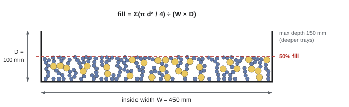
Cables are not placed in a tray in neat rows, so the usable space is less than the tray's cross-sectional area. TIA-569 limits tray fill to 50% of the inside cross-sectional area and the depth of cable to 150 mm, and good practice is to design for no more than about 25% at initial installation so that the tray can absorb future growth. The fill is calculated from the cables' cross-sectional areas:
where \(N_i\) is the number of cables of diameter \(d_i\), and \(W\) and \(D\) are the inside width and usable depth of the tray.
Worked problem
Sizing a tray for copper and fibre
A tray above a row will carry 280 Category 6A cables (7.4 mm diameter) and 12 fibre trunks of 144 fibres (13 mm diameter). Candidate trays are 300 mm and 450 mm wide, with 100 mm usable depth. Find the fill of each, and check against the 50% limit and a 25% initial target.
Show solution
- Area of one Category 6A cable: \(\pi \times 7.4^2/4 = 43.0\) mm². For 280 cables: 12,040 mm².
- Area of one trunk: \(\pi \times 13^2/4 = 132.7\) mm². For 12 trunks: 1593 mm².
- Total: 13,633 mm².
- 300 mm tray: area \(300 \times 100 = 30{,}000\) mm²; fill \(13{,}633/30{,}000 = 45\%\).
- 450 mm tray: area 45,000 mm²; fill 30%.
Answer: The 300 mm tray is under the 50% limit but leaves almost no room for growth (45%). The 450 mm tray (30%) is close to the initial target. Better still, put the trunks in a separate fibre pathway, leaving the 300 mm tray at 40% for copper alone, or move management copper to its own tray.
Weight and support
Trays must also carry the cables' weight. Each tray has a load rating, in kg/m (or lb/ft), for a given span between supports, and the supports must carry the load to the structure. A Category 6A cable weighs roughly 0.06 to 0.08 kg/m, so a few hundred of them weigh more than the tray itself.
Worked problem
Tray loading
The 450 mm tray in the previous example weighs 3.5 kg/m. The copper cables weigh 0.07 kg/m each and the trunks 0.15 kg/m each. Supports are every 1.5 m. The tray is rated 45 kg/m at that span. Check the tray, and find the load on each support (allowing for growth to the 50% fill limit).
Show solution
- Cables now: \(280 \times 0.07 + 12 \times 0.15 = 19.6 + 1.8 = 21.4\) kg/m.
- At 50% fill (scale by 50/30): \(21.4 \times 50/30 = 35.7\) kg/m. Tray loaded: \(35.7 + 3.5 = 39.2\) kg/m.
- This is within the 45 kg/m rating.
- Load per support: \(39.2 \times 1.5 = 58.8\) kg, about 0.58 kN.
Answer: The tray is adequate even at its maximum fill, and each support carries about 59 kg. Supports for overhead tray in data centres are often hung from a ceiling grid or a dedicated support structure, which must be designed by the structural engineer for these loads and, in seismic regions, braced against sideways movement.
Bend radius and pulling tension
Cables are damaged by bending them too tightly or pulling them too hard. Over-bent copper loses its pair geometry and fails crosstalk and return loss tests; over-bent fibre loses light (macrobending loss) and can crack. The standards and manufacturers set limits:
- Category 6A copper: minimum installed bend radius about 4 times the cable diameter; maximum pulling tension about 110 N (25 lbf).
- Fibre cable: minimum bend radius 10 times the cable diameter when installed and not under load, and 15 to 20 times while being pulled under tension (TIA-568.3 and manufacturer data). Bend-insensitive fibres tolerate tighter bends in the fibre itself, but the cable's structure still sets the limit.
- Pulling tension for fibre cable is set by the manufacturer from its strength members, often 600 to 2700 N for backbone cables, and must not be exceeded; long pulls use tension-limiting swivels or are measured with a dynamometer.
Tray fittings (bends, tees and waterfalls at drops) and fibre raceway fittings are made with large radii for this reason. Cable ties pulled tight crush cables and deform pairs; hook-and-loop straps, applied loosely, are the standard for data cabling.
Worked problem
Bend radius at a drop
A 144-fibre trunk is 13 mm in diameter. What minimum radius is needed where it drops from the tray into a cabinet, and during the pull?
Show solution
- Installed, not under load: \(10 \times 13 = 130\) mm.
- During pulling, under load: \(20 \times 13 = 260\) mm (using the stricter factor).
Answer: At least 130 mm at the installed drop (a waterfall fitting provides this) and 260 mm around any bend the cable passes during the pull.
Conduit for telecommunications
Conduits for telecommunications cables follow stricter rules than those for power. TIA-569 recommends:
- No more than two 90° bends (180° in total) between pull points, compared with 360° for electrical raceway.
- No more than 30 m (100 ft) between pull points.
- Fill of no more than 40% of the conduit area for three or more cables (the same figure used for power conductors), and less when long pulls or bends demand it.
- A bend radius of at least 6 times the conduit diameter for conduits up to 50 mm, and 10 times for larger conduits.
Pull boxes must be sized and placed so the cable is not bent tighter than its own limit inside them. A pull cord left in each conduit, and spare conduits, make future cables much cheaper to add.
Separation from power
Power cables can induce noise in unshielded twisted-pair copper. TIA-942 and TIA-569 give minimum separation distances that grow with the number and current of the power circuits, and shrink when the power cables are in grounded metal conduit or when the data cables are shielded. In practice most data centres simply give power and data their own pathways at different levels, crossing at right angles. Fibre is immune to electrical interference, but is still kept in separate pathways so that power work does not disturb it.
The electrical code also sets safety separations. The Canadian Electrical Code (Section 60 for communication systems and Section 56 for optical fibre cables) does not allow communication conductors in the same raceway, box or compartment as power conductors unless they are separated by a barrier or the rules otherwise permit it, and requires minimum spacing from power conductors.
Fire ratings of cables
Cables carry a large amount of combustible insulation and jacket material, and in a fire they can spread flame and smoke along the pathway. The building and electrical codes therefore require cables to be listed for the space in which they run.
In Canada, cables are tested for flame spread under CSA C22.2 No. 0.3 and marked with an FT rating. FT6 (with low flame spread and smoke) is required for cables in plenums, meaning ceiling or floor spaces used as air-handling ducts; FT4 (vertical tray test) is the common rating for risers and general use in noncombustible buildings; FT1 is the minimum general rating. The National Building Code of Canada, as adopted by each province, sets where each rating is required, with exceptions for cables in totally enclosed noncombustible raceway. The Canadian Electrical Code, Sections 56 and 60, adds the installation requirements.
A raised floor used as an air supply plenum, or a ceiling return plenum, can trigger the plenum rating requirement. Because the price difference is now small, many designers specify plenum-rated cable throughout a data centre so that any cable can be moved to any space.
Abandoned cables add fire load, block pathways and airflow, and hide live cables. Good practice, and many owners' standards, require cables that are no longer used to be removed rather than cut and left in place.
Firestopping
Wherever a pathway passes through a fire-rated wall or floor, the opening must be sealed with a tested firestop system so that the wall keeps its fire-resistance rating. In Canada, firestop systems are tested to CAN/ULC-S115, and the installed system must match a listed design for that wall type, penetrating items and opening size. Data centres use re-enterable firestop devices (pathway sleeves with built-in intumescent seals, or pillows and putty) so that cables can be added without destroying the seal.
Bonding of pathways and cabinets
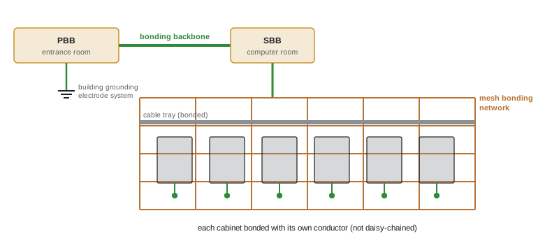
Metal pathways, racks and cabinets must be bonded so that a fault on any power circuit cannot leave them energized, and so that the whole data hall sits at a common reference potential, which helps control noise on shielded cabling. TIA-607 defines a telecommunications bonding system: a primary bonding busbar (PBB) in the entrance room or main electrical room connected to the building's grounding electrode system, secondary bonding busbars (SBB) in each telecommunications space, and a telecommunications bonding backbone conductor connecting them.
In the computer room, a mesh common bonding network (mesh-BN) is commonly installed: a grid of bare copper conductors, typically on a 600 mm to 3 m spacing, under the raised floor or above the cabinets, bonded to the building steel and the SBB. Each cabinet and rack is bonded to the mesh with its own conductor (often 6 AWG copper) and listed compression connectors, and cable trays are bonded along their length and across every joint where the tray is not listed as electrically continuous. Bonds are made with a direct, short conductor; daisy-chaining cabinets together is not acceptable because removing one cabinet would break the bond to the rest.
Lesson 9 applies these pathway principles to the extreme fibre volumes of AI clusters, and Lesson 10 continues inside the cabinet with cable managers, airflow and administration.
Common mistakes
MistakeFilling trays to 50% on day one.
InsteadDesign for about 25% initial fill so the pathway can absorb growth; 50% is the maximum, not the target.
MistakeRunning all cabling under a raised floor used for cooling air.
InsteadCables under the floor block airflow; run data overhead and keep under-floor cabling to a minimum.
MistakeUsing tight nylon cable ties on Category 6A bundles.
InsteadUse loosely applied hook-and-loop straps; crushing cables degrades transmission performance.
MistakeBending communications conduit like power conduit.
InsteadLimit telecommunications conduits to two 90° bends and 30 m between pull points.
MistakeDaisy-chaining cabinet bonds.
InsteadBond each cabinet with its own conductor to the mesh or bonding busbar.
MistakeBreaking a firestop to add cables and leaving it open.
InsteadUse re-enterable firestop devices or restore the listed system after every change.
Summary and key terms
- Pathways include ladder rack, wire basket, solid and ventilated trays, fibre raceway, conduit and under-floor trays; overhead is now preferred.
- Layer pathways by system above the cabinets, cross power at right angles, keep aisles clear and provide diverse A and B routes.
- Tray fill = total cable area ÷ tray inside area; design for about 25%, never exceed 50% or 150 mm depth.
- Check tray weight against its load rating at the support span; supports and bracing need structural design.
- Category 6A: bend radius 4 × diameter, 110 N pulling tension. Fibre: 10 × diameter at rest, 15 to 20 × while pulling.
- Telecommunications conduit: at most two 90° bends and 30 m between pull points, 40% fill.
- Separate power and data pathways; the electrical code prohibits mixing them without barriers.
- Cables must carry the fire rating required for their space; plenums need the highest rating. Firestop every rated penetration.
- TIA-607 bonding: PBB, backbone, SBBs and a mesh bonding network, with every cabinet and tray bonded individually.
- Wire basket tray
- A welded-wire cable tray that can be cut and shaped on site.
- Fibre raceway
- A plastic duct system with controlled-radius fittings for fibre cords and small cables.
- Tray fill
- The ratio of the cables' total cross-sectional area to the tray's inside area.
- Waterfall
- A curved fitting that guides cables from a tray down into a cabinet without a sharp bend.
- Minimum bend radius
- The smallest radius a cable may be bent to without damage or loss of performance.
- Pulling tension
- The force applied to a cable during installation, limited by its strength members.
- Plenum
- A space forming part of the air distribution system, such as a return-air ceiling or supply-air floor.
- Firestop system
- A tested assembly of materials that restores the fire rating of a wall or floor around a penetration.
- Abandoned cable
- Cable not terminated at both ends and not tagged for future use.
- Primary bonding busbar (PBB)
- The main telecommunications bonding busbar, connected to the building grounding electrode system.
- Secondary bonding busbar (SBB)
- A bonding busbar in a telecommunications space, connected to the PBB by the bonding backbone.
- Mesh bonding network
- A grid of bonding conductors to which all cabinets, racks and pathways in a computer room are bonded.
Practice problems
Work each problem on paper first, then reveal the answer to check.
What is the fill of a 300 × 100 mm tray holding 200 cables of 7.4 mm diameter?
Show answer
200 × 43.0 = 8600 mm²; 8600 / 30,000 = 28.7%.
How many 7.4 mm cables can a 450 × 100 mm tray hold at 25% and at 50% fill?
Show answer
At 25%: 11,250 / 43.0 = 261 cables. At 50%: 22,500 / 43.0 = 523 cables.
A tray carries 400 cables at 0.07 kg/m and weighs 3 kg/m. What load does each support carry at a 1.8 m spacing?
Show answer
(28 + 3) × 1.8 = 55.8 kg.
What is the minimum installed bend radius for a 7.4 mm Category 6A cable?
Show answer
4 × 7.4 = 29.6 mm, about 30 mm.
A 24-fibre cable is 8 mm in diameter. What is the minimum radius while pulling, using 20 times the diameter?
Show answer
20 × 8 = 160 mm.
A telecommunications conduit run has three 90° bends. What must the designer do?
Show answer
Add a pull box so that no section has more than two 90° bends (180°) between pull points.
Why are cables under a raised floor a cooling problem?
Show answer
The floor void carries supply air; cable bundles obstruct it, reducing and unbalancing airflow to perforated tiles.
Which FT rating is required for cables in a plenum, and which is common for risers?
Show answer
FT6 for plenums; FT4 for risers and general use in noncombustible buildings.
Why should each cabinet have its own bonding conductor rather than being bonded through its neighbour?
Show answer
Removing or unbolting one cabinet in a daisy chain would break the bond for all those beyond it.
Why might a designer specify plenum-rated cable throughout the facility?
Show answer
The cost difference is small, and any cable can then be moved into any space, including air plenums, without checking its rating.
Lesson quiz · 5 questions
Score 60% or more to complete this lesson.
Create a free account to save your progress, take quizzes and earn a certificate.