
DCE-320 · Lesson 1 of 12 · 34 min
TIA-942 spaces and topology
A large data centre holds tens of thousands of fibres and copper cables. Without a plan, every new server, switch and carrier circuit adds another cable run directly between two pieces of equipment, and within a few years the overhead trays are full of undocumented cable that nobody dares remove. Structured cabling replaces that tangle with a permanent, documented plant of standard links between defined spaces. Equipment then connects to that plant with short patch cords, and moves, adds and changes are made by repatching rather than by pulling new cable.
This lesson introduces the standards that govern data centre cabling, the functional spaces they define, the hierarchical star topology that connects them, and the choices between cross-connects and interconnects and between top-of-rack, end-of-row and middle-of-row layouts. The rest of the course fills in the details: media (Lesson 2), high-density fibre and loss budgets (Lesson 6), pathways (Lesson 8) and the outside plant that brings carriers into the building (Lesson 11).
The standards
Data centre cabling is designed to a small family of standards that work together:
- ANSI/TIA-942 (currently revision C, 2024), Telecommunications Infrastructure Standard for Data Centers: defines the spaces, topology, cabling and redundancy of a data centre, and a set of rating levels for the facility as a whole.
- ANSI/TIA-568 series: the generic cabling standards that set performance for balanced twisted-pair (568.2) and optical fibre (568.3) cabling and components, including test limits and polarity.
- ANSI/TIA-569: pathways and spaces, including conduits, trays, entrance facilities and the rooms that hold telecommunications equipment.
- ANSI/TIA-606: administration, meaning labelling and record keeping.
- ANSI/TIA-607: bonding and grounding of telecommunications systems.
- ANSI/BICSI 002, Data Center Design and Implementation Best Practices: a broad design reference covering architecture, electrical, mechanical and cabling, with its own availability classes.
In Canada, the CSA Group has published the TIA cabling standards as national standards (for example CSA T529 corresponds to TIA-568 and CSA T530 to TIA-569), and Canadian specifications commonly cite either the TIA or the CSA designation. The installation itself must also meet the Canadian Electrical Code, Section 56 for optical fibre cables and Section 60 for communication systems, plus the building code for fire ratings in plenums and shafts (Lesson 8).
Internationally, ISO/IEC 11801-5 and the European EN 50600 series cover the same ground with slightly different names: the "main distributor" and "zone distributor" correspond to TIA's main and horizontal distribution areas. Hyperscale operators often write their own standards that go beyond all of these, but the vocabulary of TIA-942 is the common language of the industry.
Functional spaces
TIA-942 divides a data centre into spaces by function. A small facility might combine several of them in one room, while a large campus may have dozens of each. The spaces are:
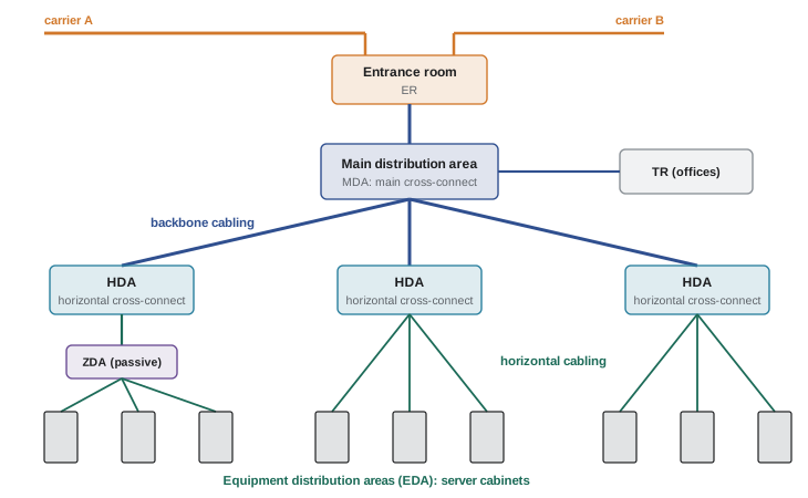
- Entrance room (ER): where carrier and campus cables enter the building and where carrier equipment (demarcation points, optical terminals) is located. It is the boundary between the outside plant and the building cabling. A colocation facility's "meet-me room", where customers cross-connect to carriers, is a form of entrance room. Large or highly available sites have two entrance rooms on opposite sides of the building.
- Main distribution area (MDA): the central point of the cabling system, holding the main cross-connect (MC) and usually the core routers and switches. Every other space is cabled back to it. Highly available designs add a second MDA.
- Intermediate distribution area (IDA): an optional second level, used in very large buildings or campuses, holding an intermediate cross-connect between the MDA and several HDAs.
- Horizontal distribution area (HDA): the distribution point for a group of rows, holding the horizontal cross-connect (HC) and often the LAN, SAN and management switches serving those rows. In a leaf-spine network, the HDA might hold the spine switches for a pod.
- Zone distribution area (ZDA): an optional consolidation point between the HDA and the equipment, such as a patch panel in an overhead enclosure or at the end of a row. It contains only passive cabling, never active equipment.
- Equipment distribution area (EDA): the racks and cabinets holding the end equipment, such as servers and storage, with the patch panels where horizontal cabling terminates.
Supporting spaces include the telecommunications room (TR), which serves offices and support areas outside the computer room, the operations centre, and the electrical and mechanical rooms, which have their own cabling for monitoring and control.
Topology: the hierarchical star
The spaces are connected in a hierarchical star. The MDA is the centre; backbone cabling runs from it to the entrance rooms, to any IDAs and to each HDA; horizontal cabling runs from each HDA (through a ZDA if one is used) to the EDAs it serves. There are no direct cables between HDAs or between EDAs in different groups in the basic topology, so any connection can be made by patching at the distribution points along a known path.
A star has three advantages for a cabling plant. First, every link has a predictable length and type, so its performance can be guaranteed in advance. Second, a change at one EDA affects only that EDA's horizontal links. Third, the cabling is independent of the network design: the same plant can support a three-tier network, a leaf-spine fabric or a storage network, because the logical topology is set by patching, not by pulling cable. TIA-942 allows direct backbone links between HDAs, or from an HDA to the ER, where a design needs them for redundancy or to bypass distance limits, but they are additions to the star, not replacements for it.
Backbone and horizontal cabling
The two levels of the star are treated differently:
- Horizontal cabling runs from the horizontal cross-connect to the outlets or patch panels in the EDA. For balanced twisted-pair copper, the permanent link (the fixed cable between two panels) is limited to 90 m, and the channel, including equipment and patch cords at both ends, to 100 m. Horizontal cabling is usually copper (category 6A) or multimode or single-mode fibre.
- Backbone cabling runs between the ER, MDA, IDAs and HDAs. Its length is limited by the applications it must support rather than by a fixed number, which in practice means optical fibre, mostly single-mode in new designs, with copper only for short links and for some carrier circuits.
Inside a data centre, the "horizontal" cabling is rarely horizontal in the building sense; it simply means the last tier of the star. Likewise, backbone cabling in a single-storey hall may run in the same overhead trays as horizontal cabling. The terms describe the cable's role in the topology, not its route.
Worked problem
Checking a copper channel length
A server cabinet is 78 m along the cable route from the HDA patch panel. The installer plans a 5 m patch cord at the HDA and a 3 m cord at the server, plus 4 m of slack on the permanent link for future re-termination. Does the channel comply?
Show solution
- Permanent link: 78 m route plus 4 m slack = 82 m, within the 90 m limit.
- Channel: 82 + 5 + 3 = 90 m, within the 100 m limit.
Answer: Yes. The permanent link is 82 m (limit 90 m) and the channel is 90 m (limit 100 m). Note that the length is measured along the actual cable route through trays, drops and slack loops, not as a straight line on the floor plan, which is often 20 to 30% shorter.
Cross-connects and interconnects
At each distribution point, cabling can be connected to the equipment in two ways:
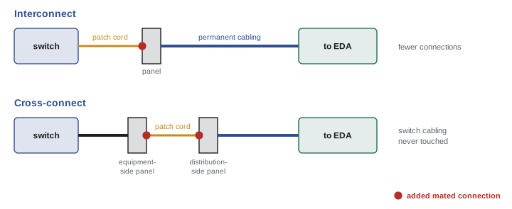
- Interconnect: the permanent cabling terminates on a patch panel, and a single patch cord runs from that panel to the switch port. Each link has one fewer connection, so it is cheaper and has less insertion loss.
- Cross-connect: the switch ports are permanently cabled to their own patch panel (an "equipment-side" panel), and the permanent cabling to the EDAs terminates on a separate panel. Changes are made only with patch cords between the two panels. The switch's cabling is never touched after installation, which protects dense line cards from repeated handling and lets changes be made in a dedicated patching area by staff who never open the network equipment cabinets.
The MDA normally uses cross-connects, because it holds the most valuable and most frequently changed connections. HDAs may use either. The extra connector in a cross-connect costs about 0.3 to 0.75 dB of optical loss and some copper performance margin, a cost that must be included in the loss budget (Lesson 6).
Equipment layouts: where the switches go
The structured cabling plan depends heavily on where the access switches (the first switch a server connects to, or the leaf in a leaf-spine fabric) are placed:
- Top-of-rack (ToR): a switch in every cabinet connects its servers with very short copper or direct-attach cables, and only the switch uplinks, usually fibre, leave the cabinet. This minimizes structured cabling to the EDAs, but needs many switches, some with unused ports, and one or two switch failures can isolate a whole cabinet.
- End-of-row (EoR): switches in a network cabinet at the end of each row connect to every server in that row through horizontal cabling. Fewer, larger switches are used more efficiently, but much more horizontal cabling is needed.
- Middle-of-row (MoR): like end-of-row with the network cabinet in the middle, halving the longest run.
Hyperscale and AI facilities almost always use ToR (or "top-of-rack plus spine row") designs because server racks arrive as fully cabled, pre-tested units and the facility cabling only needs to carry uplinks. Enterprise and colocation halls with mixed equipment more often use EoR or MoR with an HDA in each row, which looks like the classic TIA-942 star.
Worked problem
Fibre count for a row of ToR switches
A row of 20 cabinets each has two ToR switches. Each switch has four 400 Gb/s uplinks using parallel single-mode optics (8 fibres each) to spine switches in an HDA. The designer adds 25% spare. How many fibres must the row's backbone cabling carry, and how many 24-fibre MPO trunks is that?
Show solution
- Uplinks: 20 cabinets × 2 switches × 4 uplinks = 160 links.
- Fibres: 160 × 8 = 1280; with 25% spare, 1280 × 1.25 = 1600 fibres.
- Trunks: 1600 / 24 = 66.7, so 67 trunks; in practice the designer would use higher-count trunks (for example 144-fibre trunks: 1600 / 144 = 11.1, so 12 trunks).
Answer: About 1600 fibres per row, which is 67 trunks of 24 fibres or 12 trunks of 144 fibres. Higher-count trunks save tray space and installation time; Lesson 6 covers how they break out to MPO and LC connectors.
Redundancy and rating levels
TIA-942 rates data centres from Rated-1 (basic) to Rated-4 (fault tolerant) in four areas: telecommunications, architecture, electrical and mechanical. A facility's overall rating is the lowest of the four. For telecommunications the levels progress roughly as follows:
- Rated-1: a single entrance pathway and single paths throughout. Any failure or maintenance on a cable path can cause an outage.
- Rated-2: redundant active components (carrier equipment, routers, switches) but still single cable paths.
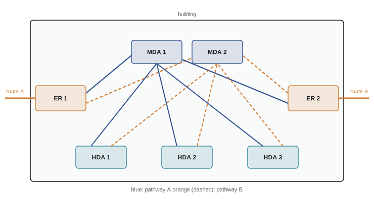
- Rated-3: two entrance pathways and diverse carrier routes into separate entrance rooms or at least separated points, redundant backbone pathways, and a second MDA recommended.
- Rated-4: fully redundant cabling with diverse backbone and horizontal pathways, a second MDA, and redundant HDAs, so no single failure of a pathway, room or component interrupts service.
BICSI 002 uses Classes F0 to F4, and the Uptime Institute's Tier I to IV classifications (covered in DCE-200) focus on power and cooling but expect the cabling to match. Whatever the scheme, the key ideas for cabling are the same: two physically separated paths for anything critical, and no single room whose loss isolates the facility.
Administration and labelling
A cabling plant is only useful if every link can be found. TIA-606 sets a scheme for labelling and records, organized around identifiers for spaces, cabinets, patch panels, ports and cables. In a data centre, cabinets are normally identified by a floor grid: if the computer room floor is laid out with a 600 mm grid, letters across one axis and numbers along the other give every tile a coordinate, and a cabinet takes the coordinate of the tile under its front right corner. A patch panel port might then be labelled "AJ05-B-24": cabinet AJ05, panel B (counting from the top), port 24.
Both ends of every cable carry the same label, which identifies both ends of the link, and the records (now usually a database or data centre infrastructure management, DCIM, system) list every link, its route, its test results and what it connects. Labels must be machine-printed and durable. Good administration is what allows abandoned cables to be identified and removed, and it is often the first thing an auditor or a new operator checks.
Designing a cabling plant: the process
A typical design proceeds in this order:
- Gather requirements: the network architecture, number of cabinets and switches, port counts and speeds, expected growth, redundancy level and the operator's own standards.
- Lay out the spaces: entrance rooms, MDAs and HDAs, located to keep runs short and pathways diverse.
- Choose the switch placement (ToR, EoR, MoR) and the cross-connect or interconnect strategy.
- Select media for each link from its length and speed (Lesson 2), and calculate loss budgets (Lesson 6).
- Count fibres and cables, plan trunks and patch panels, and allocate rack units.
- Design pathways: trays, routes, fill and separation (Lesson 8), and the entrance facilities and outside plant (Lesson 11).
- Write the labelling scheme and test requirements, and specify how the installer will document the as-built plant.
Worked problem
Sizing a patch panel space
An HDA must terminate 1600 fibres from one row (previous example) plus 400 fibres to the MDA. High-density 1U fibre panels hold 144 fibres (72 duplex LC ports), and 4U enclosures hold 576 fibres. How many rack units of panels are needed using each, and how many 45U cabinets if each cabinet keeps 10U for cable management?
Show solution
- Total fibres: 1600 + 400 = 2000.
- 1U panels: 2000 / 144 = 13.9, so 14U.
- 4U enclosures: 2000 / 576 = 3.5, so 4 enclosures = 16U.
- Usable space per cabinet: 45 − 10 = 35U, so either option fits in one cabinet, with 19 to 21U free for growth or for the spine switches themselves.
Answer: About 14 to 16U of panels, fitting in one cabinet. For a cross-connect, double this: the switch ports need their own equipment-side panels.
How this course is organized
The course moves from the overall design of a cabling plant to its parts and then back to the whole. Lesson 1 sets out the spaces and topology. Lessons 2 to 5 cover the media: choosing copper and fibre (Lesson 2), copper channel performance and Power over Ethernet (Lesson 3), the physics of optical fibre (Lesson 4) and the transceivers that set what the plant must carry (Lesson 5). Lessons 6 and 7 cover high-density fibre systems and loss budgets, then testing, certification and troubleshooting. Lessons 8 to 10 cover the physical plant: pathways and trays, cabling for AI clusters, and cabinets, cable management and administration. Lesson 11 takes the plant outside the building, and Lesson 12 brings everything together in a complete project from requirements to handover.
Common mistakes
MistakeMeasuring copper link length as a straight line on the floor plan.
InsteadMeasure along the cable route, including risers, drops and slack; the permanent link must not exceed 90 m and the channel 100 m.
MistakePutting active equipment in a zone distribution area.
InsteadA ZDA is a passive consolidation point; switches belong in the HDA or in the EDAs.
MistakeCabling the network design directly with point-to-point runs between switches.
InsteadCable a structured star between distribution areas and set the logical network with patch cords, so the plant outlives the network.
MistakeCounting two entrance cables in the same trench as diverse.
InsteadDiverse means physically separate routes and entrance points; one excavator can cut both cables in a shared trench.
MistakeLeaving the labelling scheme to the installer.
InsteadSpecify the TIA-606-style scheme, grid references and records before installation, and require as-built documentation.
Summary and key terms
- Structured cabling is a permanent, documented plant of standard links; equipment connects to it with patch cords.
- TIA-942 defines the data centre spaces and topology; TIA-568, 569, 606 and 607 cover performance, pathways, labelling and bonding; BICSI 002 is a broad best-practice reference.
- Spaces: ER (entrance), MDA (main cross-connect), IDA (optional), HDA (horizontal cross-connect), ZDA (passive consolidation) and EDA (equipment cabinets).
- The hierarchical star runs backbone cabling from the MDA and horizontal cabling from each HDA to its EDAs.
- Copper horizontal links: 90 m permanent link, 100 m channel.
- Cross-connects keep switch cabling permanent at the cost of an extra connection; interconnects are simpler and lower loss.
- ToR minimizes horizontal cabling; EoR and MoR use fewer switches but more horizontal cable.
- Rated-1 to Rated-4 levels add diverse entrances, a second MDA and redundant pathways.
- TIA-606 labelling ties every port and cable to a record; grid-based cabinet identifiers are common.
- Structured cabling
- A standards-based cabling system of permanent links between defined distribution points, connected to equipment by patch cords.
- Entrance room (ER)
- The space where carrier and campus cables enter and carrier equipment is located.
- Main distribution area (MDA)
- The central space holding the main cross-connect and usually the core network equipment.
- Horizontal distribution area (HDA)
- The space holding the horizontal cross-connect that serves a group of equipment cabinets.
- Zone distribution area (ZDA)
- An optional passive consolidation point between an HDA and the equipment.
- Equipment distribution area (EDA)
- The cabinets and racks holding end equipment such as servers.
- Backbone cabling
- Cabling between the entrance rooms, MDA, IDAs and HDAs.
- Horizontal cabling
- Cabling from the horizontal cross-connect to the equipment distribution areas.
- Permanent link
- The fixed cable between two termination points, excluding patch cords.
- Channel
- The complete end-to-end link including patch and equipment cords.
- Cross-connect
- A connection made with patch cords between two sets of permanently cabled panels.
- Interconnect
- A connection made with a patch cord directly from a panel to the equipment.
- Top-of-rack (ToR)
- A layout with an access switch in every cabinet.
- Meet-me room
- A space in a colocation facility where customers cross-connect to carriers.
Practice problems
Work each problem on paper first, then reveal the answer to check.
Name the six TIA-942 functional spaces in order from the carrier to the server.
Show answer
Entrance room, main distribution area, intermediate distribution area (optional), horizontal distribution area, zone distribution area (optional), equipment distribution area.
A copper permanent link is 86 m. What is the longest total patch cord length allowed in the channel?
Show answer
100 − 86 = 14 m in total for both ends.
Why must a ZDA not contain switches?
Show answer
TIA-942 defines it as a passive consolidation point; active equipment there would create an extra network tier and power, cooling and access needs in an uncontrolled location.
Give two advantages of a cross-connect over an interconnect, and one disadvantage.
Show answer
Advantages: switch cabling is never disturbed; changes are made in a dedicated patching area. Disadvantage: an extra mated connection adds loss and cost and needs more panel space.
A row has 16 cabinets with two ToR switches each; each switch has eight uplinks of 2 fibres. How many fibres, with 20% spare?
Show answer
16 × 2 × 8 × 2 = 512; × 1.2 = 614.4, so about 615 (in practice 624 fibres, the next multiple of 24).
What distinguishes a Rated-3 telecommunications design from Rated-2?
Show answer
Rated-3 adds diverse entrance pathways and carrier routes, redundant backbone pathways and (recommended) a second MDA, not just redundant equipment.
Why is backbone cabling in new data centres mostly single-mode fibre?
Show answer
Backbone lengths and future speeds exceed what copper and often multimode can carry; single-mode supports long reach and successive generations of optics.
How many 1U 144-fibre panels are needed to terminate 3000 fibres?
Show answer
3000 / 144 = 20.8, so 21 panels (21U).
A cabinet sits on grid tile BC14 and has panels A to D. Write a label for port 7 of panel C.
Show answer
BC14-C-07 (format varies with the site scheme, but cabinet, panel and port must all be identified).
Why is EoR more common in enterprise halls than in AI clusters?
Show answer
Enterprise halls have mixed equipment and benefit from fewer, larger shared switches; AI clusters arrive as pre-cabled racks with ToR or in-rack switches and need only uplink fibre.
Lesson quiz · 5 questions
Score 60% or more to complete this lesson.
Create a free account to save your progress, take quizzes and earn a certificate.