
DCE-320 · Lesson 5 of 12 · 27 min
Transceivers, breakouts and high-speed interconnect
The cabling plant exists to connect transceivers, and the transceivers the network team chooses decide which fibre type, connector and fibre count every link needs. A plant designed without knowing them may have the wrong connectors, too few fibres, or the wrong fibre grade. Equally, the optics are among the largest costs and power loads in a modern network: in a large AI cluster there can be tens of thousands of modules, each drawing 10 to 25 W. This lesson explains how high-speed Ethernet and InfiniBand links are built from lanes, the form factors and optical interfaces in use, breakout cabling, copper and active cables, and the newer approaches of linear and co-packaged optics.
Lanes, modulation and naming
A high-speed port is built from parallel electrical lanes between the switch chip (or network adapter) and the module. Each generation has raised the rate per lane:
| Lane rate | Modulation | Symbol rate | Typical ports |
|---|---|---|---|
| 25 Gb/s | NRZ (2 levels) | 25.8 GBd | 25G SFP28, 100G QSFP28 (4 lanes) |
| 50 Gb/s | PAM4 (4 levels) | 26.6 GBd | 200G QSFP56, 400G QSFP-DD (8 lanes) |
| 100 Gb/s | PAM4 | 53.1 GBd | 400G QSFP112, 800G QSFP-DD800 and OSFP |
| 200 Gb/s | PAM4 | about 106–113 GBd | 1.6T OSFP (8 lanes) |
Optical interfaces are named by speed, medium and reach. In IEEE Ethernet names such as 400GBASE-DR4, the letters after the dash give the reach (SR short reach on multimode, DR 500 m single-mode, FR 2 km, LR 10 km, ER 40 km, ZR 80 km and beyond) and the final number the count of lanes or wavelengths. Industry multi-source agreements (MSAs) define further variants, such as 2xDR4 and 2xFR4 for 800G, which are two 400G interfaces in one module.
Pulse amplitude modulation with four levels (PAM4) doubled the bits per symbol, but it squeezes three eyes into the space of one, so each eye has about one-third of the amplitude of an NRZ eye, a penalty of about 9.5 dB. PAM4 links therefore depend on forward error correction (FEC), which corrects a raw bit error ratio of around \(2 \times 10^{-4}\) to effectively error-free, and are more sensitive to loss and reflections in the cabling (Lesson 4).
Form factors
Pluggable modules come in standard form factors defined by MSAs:
- SFP family (one lane): SFP+ (10G), SFP28 (25G), SFP56 (50G), SFP112 (100G). Used for server connections and management.
- QSFP family (four lanes): QSFP28 (100G), QSFP56 (200G), QSFP112 (400G).
- QSFP-DD (eight lanes, double density): 400G and 800G, backward compatible with QSFP modules.
- OSFP (eight lanes): a slightly larger module with more room for power and heat, used for 800G and 1.6T, and common in AI networks. OSFP-XD extends to sixteen lanes.
Larger modules matter because the power of each module is rising. A 400G DR4 module draws about 8 to 12 W, an 800G module about 13 to 18 W and a 1.6T module 20 W or more. A 64-port switch full of 800G modules can therefore spend 1 kW on optics alone, comparable to the switch chip.
Optical interfaces and their cabling
Each optical interface implies a particular cabling plant. The designer needs the fibre type, connector and fibre count for every interface the network will use, now and in the next generation:
| Interface | Fibre | Connector and fibres | Reach |
|---|---|---|---|
| 100GBASE-SR4 | Multimode | MPO-12, 8 fibres used | 70 m OM3, 100 m OM4 |
| 400GBASE-SR8 | Multimode | MPO-16, 16 fibres | 70 m OM3, 100 m OM4 |
| 400GBASE-SR4.2 | Multimode | MPO-12, 8 fibres | 70 m OM3, 100 m OM4, 150 m OM5 |
| 400GBASE-DR4 | Single-mode | MPO-12 (APC), 8 fibres | 500 m |
| 400GBASE-FR4 | Single-mode | Duplex LC | 2 km |
| 800G 2xDR4 / DR8 | Single-mode | MPO-16 or two MPO-12, 16 fibres | 500 m |
| 800G 2xFR4 | Single-mode | Two duplex LC (or CS) | 2 km |
| 400ZR / ZR+ | Single-mode | Duplex LC, DWDM coherent | 80 km to hundreds of km |
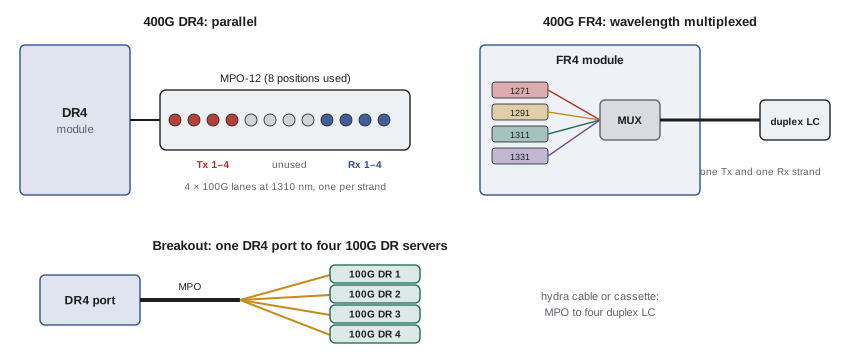
The trend in large data centres has been toward single-mode fibre for nearly everything above the server, because single-mode DR and FR optics now cost little more than multimode SR optics, single-mode reaches across any hall, and it supports future generations. Multimode remains common for short links within rows and in enterprise facilities.
Breakouts
A parallel interface can be split into independent lower-speed ports. A 400G DR4 port, for example, is four 100G lanes on four fibre pairs, and with a breakout cable or cassette it can connect to four separate 100G DR servers. Similarly, an 800G 2xDR4 port can serve two 400G DR4 ports or eight 100G ports, and an 800G 2xFR4 module two 400G FR4 ports.
Breakouts increase the effective port count of a switch: a 64-port 800G switch can serve 128 servers at 400G, or 512 at 100G. They also shape the cabling: a breakout is usually built either as a hydra cable (an MPO on one end and several duplex LCs on the other) for short in-rack links, or through structured cabling with MPO trunks to cassettes or fan-out panels in each server cabinet (Lesson 6).
Worked problem
Ports from a switch with breakouts
A leaf switch has 64 ports of 800G. Half are used for uplinks. The rest connect to servers with 400G network adapters using 2x400G breakouts. How many servers does the leaf serve, and what is the oversubscription?
Show solution
- Downlinks: 32 ports × 2 = 64 server connections at 400G = 25.6 Tb/s.
- Uplinks: 32 × 800G = 25.6 Tb/s.
- Ratio: 25.6 : 25.6 = 1 : 1.
Answer: 64 servers, non-blocking (1:1). For general-purpose computing a designer might use more downlinks and accept 3:1 oversubscription; AI training fabrics are normally built non-blocking.
Copper and active cables
Within a cabinet or between adjacent cabinets, the cheapest and lowest-power links are copper:
- Direct-attach copper (DAC): passive twinaxial cable with module-shaped plugs. It draws almost no power and adds almost no latency, but its reach shrinks as lane rates rise: about 3 to 5 m at 25 Gb/s per lane, about 2 to 3 m at 100 Gb/s per lane, and around 1 to 2 m at 200 Gb/s per lane.
- Active electrical cables (AEC): twinax with retimer or redriver chips in the plugs, reaching about 5 to 7 m with thinner cable, at a few watts per end.
- Active optical cables (AOC): a pair of optical engines joined by a fixed fibre cable, reaching up to about 100 m. Simple to install, but the whole cable must be replaced if either end fails, and it cannot be routed through structured cabling.
In AI systems, copper has become important again. Rack-scale systems connect tens of accelerators inside a rack through copper backplanes or cable cartridges, avoiding optics entirely for the highest-bandwidth links, because copper costs and draws far less. The design consequence is that more of the network is inside the rack, and the structured plant connects racks to each other.
Power, heat and reliability of optics
A module's power has three parts: the lasers and drivers, the receivers, and the digital signal processor (DSP) that equalizes, retimes and handles FEC for PAM4 signals. In an 800G module, the DSP can account for around half the power.
# Optics count and power for a two-tier leaf-spine fabric.
gpus = 4096          # one 400G NIC port per GPU
nic_gbps = 400
port_gbps = 800      # switch ports are 800G, split 2 x 400G to NICs
radix = 64           # 800G ports per switch

leaf_down = radix // 2                   # ports toward servers
nics_per_leaf = leaf_down * port_gbps // nic_gbps
leaves = gpus // nics_per_leaf
uplinks = leaves * (radix // 2)          # non-blocking: half the ports go up
spines = uplinks // radix

print(f"leaves {leaves}, spines {spines}, leaf-spine links {uplinks}")

# Every link needs a module at each end
nic_modules = gpus                       # 400G modules at the NICs
leaf_down_modules = leaves * leaf_down   # 800G modules, each feeding two NICs
fabric_modules = 2 * uplinks             # 800G modules on leaf and spine

watts = {"400G": 8.0, "800G": 15.0}      # typical with DSP
p_dsp = nic_modules * watts["400G"] + (leaf_down_modules + fabric_modules) * watts["800G"]
p_lpo = 0.55 * p_dsp                     # linear optics without DSP, rough
print(f"modules: 400G {nic_modules}, 800G {leaf_down_modules + fabric_modules}")
print(f"optics power with DSP {p_dsp / 1000:.1f} kW, linear optics about {p_lpo / 1000:.1f} kW")
print(f"per GPU {p_dsp / gpus:.1f} W")leaves 64, spines 32, leaf-spine links 2048 modules: 400G 4096, 800G 6144 optics power with DSP 124.9 kW, linear optics about 68.7 kW per GPU 30.5 W
The result shows why optics have become a design concern for facilities as well as networks: more than 100 kW for one cluster's optics, about 30 W per accelerator, all dissipated at the front of switch and server faceplates, where airflow must remove it. Modules run hot (case temperatures of 70 °C or more), and their failure rate rises with temperature, so cooling at the faceplate is part of the facility design.
Linear and co-packaged optics
Two developments aim to cut optics power:
- Linear pluggable optics (LPO) remove the DSP from the module and rely on the switch chip's own serializer to drive the optics directly, saving roughly 40 to 50% of module power and reducing latency, at the cost of tighter limits on the electrical channel and on interoperability.
- Co-packaged optics (CPO) place the optical engines on the same package as the switch chip, eliminating the long electrical traces to the faceplate. Fibres leave the switch from the package itself, with external laser sources that can be replaced from the front panel. CPO switches began shipping for AI networks in the mid-2020s; they save power but change maintenance, since an optical failure may require replacing more than a pluggable module.
For the cabling plant, CPO and LPO change little: the switch still presents fibre ports, usually MPO or duplex single-mode, and the same plant serves them. The decision lies with the network team, but the designer must know the connector types and fibre counts.
Planning for the next generation
A cabling plant should outlast several generations of optics. Practical rules follow from the trends above:
- Provide single-mode fibre to every cabinet, even where multimode is used today.
- Choose MPO trunk fibre counts that divide evenly into the likely interfaces: 16-fibre and 8-fibre multiples suit 8-lane optics; 24-fibre and 12-fibre multiples suit older 4-lane designs (Lesson 6 discusses base-8, base-12 and base-16 systems).
- Keep loss budgets well below the most demanding application expected: a 500 m DR link allows about 3 dB of channel loss, but some future optics may allow less.
- Use APC connectors for single-mode MPO trunks.
- Leave pathway space for cable count growth, since each generation often doubles the fibres per switch.
Worked problem
Fibre count for a cabinet row
A row has 10 server cabinets, each with 4 servers having two 400G DR4 ports (8 fibres each). Each cabinet needs those fibres plus 50% spare. How many fibres per cabinet, and how many 16-fibre MPO trunks?
Show solution
- Active fibres per cabinet: \(4 \times 2 \times 8 = 64\).
- With 50% spare: 96 fibres.
- Trunks: \(96 / 16 = 6\) MPO-16 trunks, or one 96-fibre trunk cable with six MPO-16 legs.
Answer: 96 fibres, six MPO-16 connections, per cabinet; 960 fibres for the row. The same plant would also carry 800G DR8 ports later (16 fibres each), at six ports per cabinet.
Common mistakes
MistakeDesigning the plant before knowing the optics.
InsteadAgree the interface types for this and the next generation first; they set fibre type, connector and count.
MistakeAssuming DAC reach stays the same at higher lane rates.
InsteadPassive copper reach shrinks each generation, to about 1–2 m at 200 Gb/s per lane.
MistakeIgnoring optics power in the facility design.
InsteadCount modules and their watts; in AI clusters they reach hundreds of kilowatts.
MistakeRunning AOCs through structured cabling pathways as if they were permanent cabling.
InsteadAOCs are equipment cords, replaced whole; plan them as such.
MistakeMixing multimode SR and single-mode DR optics on the same trunk.
InsteadEach optic needs its own fibre type; label trunks clearly.
Summary and key terms
- High-speed ports are built from lanes: 25 G NRZ, then 50, 100 and 200 Gb/s PAM4.
- PAM4 needs FEC and is more sensitive to loss and reflections.
- Form factors include SFP, QSFP, QSFP-DD and OSFP; module power rises with speed.
- Each interface sets the fibre type, connector and fibre count: SR multimode, DR/FR single-mode.
- Parallel optics can be broken out into lower-speed ports.
- Optics power is large; LPO and CPO reduce it; plan the plant for future generations.
- Lane
- One electrical or optical channel within a port.
- PAM4
- Four-level pulse amplitude modulation, two bits per symbol.
- FEC
- Forward error correction, which corrects bit errors at the receiver.
- QSFP-DD
- An eight-lane, double-density QSFP form factor.
- OSFP
- An eight-lane form factor with more room for power and heat.
- Breakout
- Splitting a parallel port into several lower-speed ports.
- DAC
- Direct-attach copper cable.
- AOC
- Active optical cable with built-in optics at both ends.
- LPO
- Linear pluggable optics without a DSP in the module.
- CPO
- Co-packaged optics on the switch chip package.
Practice problems
Work each problem on paper first, then reveal the answer to check.
How many bits per symbol does PAM4 carry?
Show answer
Two.
What does DR in 400GBASE-DR4 indicate?
Show answer
Single-mode, 500 m reach.
How many fibres does 400GBASE-SR8 use?
Show answer
16.
Which connector does 400GBASE-FR4 use?
Show answer
Duplex LC.
How many 100G servers can one 800G 2xDR4 port serve with breakouts?
Show answer
Eight.
Energy per bit of an 800G module at 16 W?
Show answer
16/800×10⁹ = 20 pJ/bit.
Why are AOCs not part of structured cabling?
Show answer
They are fixed point-to-point cords with optics built in, replaced whole.
About how much power can LPO save?
Show answer
Roughly 40–50% of module power.
A leaf with 48 downlinks and 16 uplinks at the same speed: oversubscription?
Show answer
3:1.
Fibres for 6 servers each with one 800G DR8 port, plus 50% spare?
Show answer
6 × 16 × 1.5 = 144.
Lesson quiz · 5 questions
Score 60% or more to complete this lesson.
Create a free account to save your progress, take quizzes and earn a certificate.