
DCE-320 · Lesson 6 of 12 · 34 min
High-density fibre, MPO and loss budgets
A modern data hall carries thousands of fibres between each row and the network areas, and an AI cluster can need hundreds of thousands. Terminating each fibre individually in the field would take months and leave room for many errors. Instead, high-density plants are built from factory-terminated multi-fibre trunks, MPO connectors and modular cassettes, assembled like building blocks. This raises two design problems that the rest of this lesson addresses: making sure every transmitter ends up connected to a receiver (polarity), and making sure the light that arrives is strong enough (the loss budget).
Building blocks of a high-density plant
A typical pre-terminated plant has four kinds of components:
- Trunk cables: multi-fibre cables, typically 24 to 288 fibres in a data hall (and up to several thousand in campus and AI backbones), factory-terminated with MPO connectors on both ends and supplied at measured lengths with test reports.
- Panels or enclosures: rack-mounted housings that hold modules or adapter plates, often 1U to 4U.
- Cassettes (modules): small units that plug into the panel. A breakout cassette has one or more MPO connectors at the back, joined inside by short fanout fibres to LC or VSFF ports at the front, converting a trunk to duplex connections. An MPO pass-through adapter plate simply joins the trunk to an MPO patch cord for parallel optics.
- Patch and equipment cords: LC, VSFF or MPO cords from the panels to the transceivers.
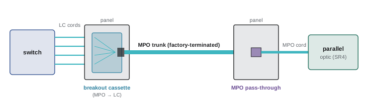
Field termination is still used where lengths cannot be known in advance, such as in outside plant and some campus backbones. The usual method is fusion splicing: the fibre ends are cleaved, aligned and fused with an electric arc, either to factory-made pigtails in a splice enclosure or to a splice-on connector. A good fusion splice loses less than 0.1 dB. Ribbon fibres can be mass-fusion spliced 12 at a time, which is how very high fibre-count cables are joined (Lesson 11).
MPO connectors
An MPO connector holds 8, 12, 16 or 24 fibres in one rectangular ferrule, in one row of 12 or 16 (or two rows for 24 and 32). Two steel guide pins on one connector enter two holes on the other to align the ferrules; the connector with pins is called male (pinned) and the one without female (unpinned). Every mated pair must have exactly one pinned connector. Transceivers have pins, so the cords that plug into them are unpinned; trunks are commonly pinned at both ends, with unpinned cords plugging into them through the panel adapters. Pinned-to-pinned mating can damage the pins, and unpinned-to-unpinned mating leaves the fibres misaligned.
Each MPO connector also has a key on one side of its body. Fibre positions are numbered 1 to 12 from left to right when the connector is viewed with the key up. Adapters are either key-up to key-down, which keeps position 1 opposite position 1, or key-up to key-up, which places position 1 opposite position 12. These details decide polarity.
Single-mode MPO connectors used with DR4 and similar optics are usually APC (angled, green), while multimode MPO connectors are flat (UPC or PC). As with duplex connectors, APC and flat MPOs must not be mated.
Polarity
A duplex optic transmits on one fibre and receives on the other. A parallel optic such as 100GBASE-SR4 or 400GBASE-DR4 transmits on four fibres (positions 1 to 4 of an MPO-12) and receives on four (positions 9 to 12), leaving 5 to 8 unused. Polarity is the set of rules that make every transmitter at one end arrive at a receiver at the other. Get it wrong and the link simply does not come up, with no damage but plenty of lost time.
TIA-568.3 defines three types of MPO trunk and cord:
- Type A (straight): position 1 at one end connects to position 1 at the other. The cable is keyed key-up at one end and key-down at the other.
- Type B (reversed): position 1 connects to position 12, 2 to 11 and so on. Both ends are key-up.
- Type C (pair-flipped): adjacent pairs are swapped, so 1 connects to 2 and 2 to 1, 3 to 4 and 4 to 3, and so on.
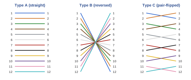
For a parallel optic, the transmitters at positions 1 to 4 at one end must reach receivers at positions 12 to 9 at the other. In other words, the whole channel must behave as a reversal (Type B). Since two reversals cancel, the rule is easy to apply: count the Type B elements in the channel (trunks, cords and any reversing adapters). If the count is odd, the channel is reversed and parallel optics work. TIA-568.3 names two standard methods for parallel optics:
- Method A: a Type A trunk, a Type A MPO cord at one end and a Type B MPO cord at the other. One reversal in total.
- Method B: Type B trunk with Type B cords at both ends, using key-up to key-up adapters throughout. Three reversals, which is equivalent to one.
Duplex channels use the same principle with A-to-B duplex cords (which cross transmit and receive) and with cassettes whose internal wiring is matched to the trunk type. Manufacturers sell "universal" polarity systems where the trunks, cassettes and cords are designed so that any channel built from them works. The safest practice is to pick one method for the whole site, document it, and buy components only from that system.
Worked problem
Checking polarity in a parallel channel
A 400GBASE-DR4 channel is built from an MPO cord at the switch, a trunk, and an MPO cord at the server. The installer has a Type B trunk, one Type B cord and one Type A cord. Will the link work? What if both cords were Type A?
Show solution
- Count Type B elements: trunk (B) + one cord (B) = 2. An even number means the reversals cancel, so the channel is straight (Type A) overall.
- Position 1 (transmit) at one end would arrive at position 1 (transmit) at the other: the link fails.
- With both cords Type A, the count is 1 (the trunk only), which is odd: the channel is reversed and the link works.
Answer: The first combination fails; the second works. A Type B trunk with two Type B cords (Method B) would also work, with 3 reversals.
Base-8, base-12 and base-16
Most trunks and cassettes were historically designed around 12-fibre MPOs ("base-12"). Parallel optics with four lanes use only 8 of those 12 fibres, so a base-12 plant used directly for SR4 or DR4 leaves a third of its fibres dark. Two solutions are common:
- Base-8 or base-16 systems: trunks built from 8-fibre or 16-fibre groups, with MPO-8 or MPO-16 connectors, match 4-lane and 8-lane optics exactly.
- Conversion modules: a cassette that takes three MPO-12 inputs (36 fibres) and presents four MPO-8 outputs (32 fibres, with 4 spare), recovering most of the unused fibres at the cost of an extra connection.
Worked problem
Fibre utilization of base-12 and base-8 trunks
A designer needs 36 links of 400GBASE-DR4 (8 fibres each) between two rows. Compare a base-12 plant using 144-fibre trunks of 12 MPO-12 connectors with a base-8 plant using 128-fibre trunks of 16 MPO-8 connectors.
Show solution
- Fibres actually used: 36 × 8 = 288.
- Base-12: one link per MPO-12, so 36 MPO-12 connectors, which is 3 trunks of 144 fibres = 432 fibres installed. Utilization 288 / 432 = 67%.
- Base-8: one link per MPO-8, so 36 MPO-8 connectors, which is 36/16 = 2.25 trunks, so 3 trunks of 128 fibres = 384 fibres (with 12 MPO-8 connectors spare for growth). Utilization of the connectors used: 100%.
Answer: The base-12 plant uses two-thirds of its fibres; the base-8 plant uses all the fibres in its connected MPOs and leaves 12 spare links. For 4-lane parallel optics, base-8 (or base-16 for 8-lane optics) avoids paying for and routing dark fibre.
Loss budgets
Every optical interface standard sets a maximum channel insertion loss: the total loss of light from the transmitter to the receiver that the optics are guaranteed to tolerate. The cabling designer must show that each channel's calculated loss is below that maximum. The channel loss is the sum of three parts:
where \(\alpha\) is the fibre attenuation in dB/km, \(L\) the length in km, \(N_c\) the number of mated connector pairs (not counting the connections at the transceivers themselves, which are included in the optics' own budget), \(IL_c\) the loss per mated pair, \(N_s\) the number of splices and \(IL_s\) the loss per splice.
The values to use depend on the components:
- Connectors: TIA-568.3 allows up to 0.75 dB per mated pair. Factory-terminated "low-loss" LC and MPO connectors are typically specified at 0.15 to 0.35 dB maximum, and a design using them must use the manufacturer's guaranteed maximum, not the typical value.
- Splices: up to 0.3 dB by standard; under 0.1 dB is typical for fusion splices.
- Fibre: 3.5 dB/km at 850 nm for multimode, and 0.4 to 1.0 dB/km for single-mode depending on wavelength and whether the specification or the measured value is used.
| Interface | Fibre | Reach | Max channel insertion loss |
|---|---|---|---|
| 100GBASE-SR4 | OM3 | 70 m | 1.8 dB |
| 100GBASE-SR4 | OM4 | 100 m | 1.9 dB |
| 400GBASE-DR4 | Single-mode | 500 m | 3.0 dB |
| 400GBASE-FR4 | Single-mode | 2 km | 4.0 dB |
| 100GBASE-LR4 | Single-mode | 10 km | 6.3 dB |
Worked problem
Multimode channel with cross-connects
A 100GBASE-SR4 channel on OM4 runs 90 m and passes through cross-connects at both ends, giving four mated MPO pairs. Check the loss budget (1.9 dB) with low-loss MPOs at 0.35 dB maximum, and with standard MPOs at 0.75 dB.
Show solution
- Fibre: \(3.5 \times 0.090 = 0.32\) dB.
- Low-loss connectors: \(4 \times 0.35 = 1.40\) dB. Total \(0.32 + 1.40 = 1.72\) dB, which is 0.18 dB under the 1.9 dB limit.
- Standard connectors: \(4 \times 0.75 = 3.00\) dB. Total 3.32 dB, which exceeds the limit by 1.4 dB.
Answer: The channel works only with low-loss MPOs, and with only 0.18 dB of margin. To gain margin, remove a cross-connect (use an interconnect at one end), shorten the link or move to single-mode. Short-reach multimode budgets leave room for only a few connections.
Worked problem
Single-mode channel
A 400GBASE-DR4 channel runs 420 m on single-mode fibre, with six mated APC MPO pairs at 0.35 dB maximum and no splices. Using 0.5 dB/km for the fibre, find the loss and margin against 3.0 dB. Then repeat using the TIA-568.3 inside plant maximum of 1.0 dB/km.
Show solution
- Fibre: \(0.5 \times 0.42 = 0.21\) dB. Connectors: \(6 \times 0.35 = 2.10\) dB. Total 2.31 dB; margin 0.69 dB.
- With 1.0 dB/km: fibre 0.42 dB, total 2.52 dB; margin 0.48 dB.
Answer: The channel passes either way, with about 0.5 to 0.7 dB of margin. In single-mode channels at these lengths the connectors, not the fibre, dominate the loss.
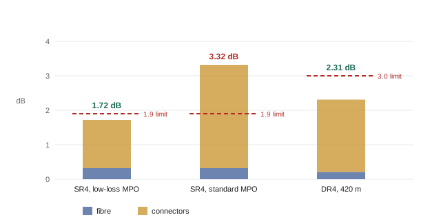
A designer should keep a margin, commonly 0.5 dB or more, for connector wear, contamination and repairs, because a link at the edge of its budget may pass on day one and fail intermittently a year later. Where margins are tight, the design can reduce the number of connections, use higher-grade connectors, or choose optics with larger budgets.
Testing
Every installed link is tested before it is accepted. TIA-568.3 and the related test standards define two tiers:
- Tier 1 (basic) testing uses an optical loss test set (OLTS), a calibrated light source at one end and a power meter at the other, to measure insertion loss at each wavelength, plus length and polarity. The tester is first referenced with test cords, usually using the one-cord reference method, which includes both end connections in the result. Multimode sources must meet an "encircled flux" launch condition so that results are repeatable. MPO testers measure all fibres of an MPO in one step and check polarity at the same time.
- Tier 2 (extended) testing adds an optical time-domain reflectometer (OTDR), which sends pulses into the fibre and measures the light reflected and scattered back. It shows the location and loss of each connector, splice and bend, which helps find faults and verify workmanship, and is standard for outside plant and long backbone links.
The test results, by link, are part of the as-built documentation and the basis for the manufacturer's warranty, which for structured cabling systems commonly runs 20 years or more if the installer is certified and the links pass.
Inspect and clean
Contamination is the most common cause of fibre link failure. A single particle of dust on a 9 µm single-mode core can block much of the light, and mating a dirty connector can transfer and grind the dirt into both end faces. The rule is "inspect before you connect": look at every end face with a fibre microscope or automated inspection probe before mating, clean it if needed with a dry cleaning tool (or a solvent followed by a dry clean for stubborn contamination), and inspect again. IEC 61300-3-35 sets pass/fail criteria for scratches and defects in zones around the core. Dust caps keep connectors clean in storage but are not themselves clean, so a connector fresh from its cap still needs inspection.
Lesson 7 develops testing further: reference methods, design-based limits, reading OTDR traces, test specifications and troubleshooting.
Common mistakes
MistakeMating two pinned or two unpinned MPO connectors.
InsteadEach mated pair needs one pinned and one unpinned connector; transceivers are pinned, so their cords are unpinned.
MistakeMixing polarity methods and component types across a site.
InsteadChoose one TIA-568.3 method or one manufacturer's system, document it, and count Type B elements to check each channel.
MistakeUsing typical connector loss in the loss budget.
InsteadUse the guaranteed maximum per mated pair, and keep at least about 0.5 dB of margin.
MistakeCounting the transceiver connections in the channel loss.
InsteadThe connections at the optics are included in the optics' own budget; count only mated pairs in the cabling.
MistakeConnecting a fibre straight from its dust cap without inspection.
InsteadInspect, clean if needed, and inspect again before every mating.
Summary and key terms
- High-density plants use factory-terminated MPO trunks, panels, cassettes and cords; field fusion splicing is used where lengths are unknown.
- MPO connectors hold 8 to 24 fibres; one connector of each mated pair must be pinned.
- Type A cables are straight, Type B reversed and Type C pair-flipped.
- Parallel optics need a reversed channel: an odd number of Type B elements (Method A or Method B).
- Base-8 and base-16 systems match 4- and 8-lane optics and avoid unused fibres in base-12 plants.
- Channel loss = fibre attenuation × length + connector pairs × loss per pair + splices × loss per splice.
- Short-reach multimode budgets (1.8–1.9 dB for SR4) allow only a few low-loss connections; connectors dominate short single-mode budgets too.
- Tier 1 testing measures loss, length and polarity; Tier 2 adds an OTDR trace. Inspect and clean every connector before mating.
- Trunk cable
- A factory-terminated multi-fibre cable with MPO connectors, used as permanent cabling.
- Cassette
- A module that converts an MPO trunk to LC or VSFF ports, or passes MPO connections through.
- Fusion splice
- A permanent joint made by melting two fibre ends together with an electric arc.
- Pinned (male) connector
- An MPO connector with guide pins that align it with an unpinned connector.
- Polarity
- The arrangement that connects each transmitter to a receiver at the far end.
- Type B cable
- An MPO cable that reverses fibre positions (1 to 12, 2 to 11 …).
- Base-8
- A trunk and connector system built in groups of 8 fibres to match 4-lane parallel optics.
- Channel insertion loss
- The total optical loss between the transceivers of a link.
- Mated pair
- Two connectors joined in an adapter; the unit of connector loss.
- Loss budget
- The comparison of a channel's calculated loss with the maximum allowed by the application.
- OLTS
- Optical loss test set: a light source and power meter for measuring insertion loss.
- OTDR
- Optical time-domain reflectometer: an instrument that locates and measures events along a fibre.
- Encircled flux
- A defined multimode launch condition that makes loss measurements repeatable.
Practice problems
Work each problem on paper first, then reveal the answer to check.
A channel has a Type A trunk and Type A cords at both ends. Will a parallel optic work?
Show answer
No: there are no Type B elements (an even count), so the channel is straight and transmitters reach transmitters.
In a 12-fibre MPO for SR4, which positions transmit and which receive, and which are unused?
Show answer
Positions 1–4 transmit, 9–12 receive, and 5–8 are unused.
How many 400GBASE-SR8 links (16 fibres each) can a 144-fibre base-12 trunk support if each link uses one MPO-24? And a 128-fibre base-16 trunk?
Show answer
Base-12: 144 / 24 = 6 links (96 fibres used, 67%). Base-16: 128 / 16 = 8 links (100%).
Calculate the loss of a 60 m OM4 channel with three mated MPO pairs at 0.35 dB. Does it meet 100GBASE-SR4?
Show answer
3.5 × 0.06 = 0.21 dB; 3 × 0.35 = 1.05 dB; total 1.26 dB, under 1.9 dB with 0.64 dB margin.
A 1.8 km 400GBASE-FR4 channel has four LC pairs at 0.25 dB and two splices at 0.1 dB. With 0.5 dB/km, what is the margin against 4.0 dB?
Show answer
0.9 + 1.0 + 0.2 = 2.1 dB; margin 1.9 dB.
What is the maximum number of 0.35 dB mated pairs in a 100 m OM4 SR4 channel, keeping 0.2 dB margin?
Show answer
Fibre 0.35 dB; allowance 1.9 − 0.2 − 0.35 = 1.35 dB; 1.35 / 0.35 = 3.9, so three pairs.
Why must MPO connectors be inspected even straight out of a new package?
Show answer
Dust caps and packaging can leave contamination; a particle on the core blocks light and is ground into both end faces when mated.
What does an OTDR show that an OLTS does not?
Show answer
The location and loss of each event along the link (connectors, splices, bends, breaks), not just the total loss.
Give two ways to recover loss budget in a tight multimode channel.
Show answer
Replace a cross-connect with an interconnect to remove mated pairs; use lower-loss connectors; shorten the link; or move to single-mode optics with larger budgets.
A Method B channel uses a Type B trunk. What type of MPO cords are used at each end?
Show answer
Type B cords at both ends (three reversals, which is odd, so the channel is reversed).
Lesson quiz · 5 questions
Score 60% or more to complete this lesson.
Create a free account to save your progress, take quizzes and earn a certificate.