
DCE-320 · Lesson 3 of 12 · 33 min
Copper channel performance and Power over Ethernet
Lesson 2 compared media at the level of categories and reach. To design, specify and accept a copper plant, a designer needs to know what those categories actually guarantee: which electrical parameters are tested, how a channel differs from a permanent link, why a link that passes at installation can fail when its neighbours are added, and how the same cable carries both data and tens of watts of power. Copper is no longer the medium for the fastest links in a data centre, but it still connects management networks, out-of-band consoles, building systems, cameras, access control and wireless access points, often in the thousands, and its failures are just as disruptive.
This lesson covers the channel and permanent-link models, the transmission parameters that define a category, alien crosstalk, shielding and bonding, field certification, and the electrical and thermal design of Power over Ethernet (PoE).
Channels and permanent links
TIA-568.2 and ISO/IEC 11801 define performance for two test configurations:
- The permanent link: the fixed part of the cabling, from the patch panel port to the outlet or the far patch panel, up to 90 m. It is what the installer builds and certifies, and what stays in place for twenty years or more.
- The channel: the end-to-end path the equipment sees, which adds the patch cords and equipment cords at both ends. A channel may be up to 100 m long, with at most 10 m of cords in total, and up to four connections.
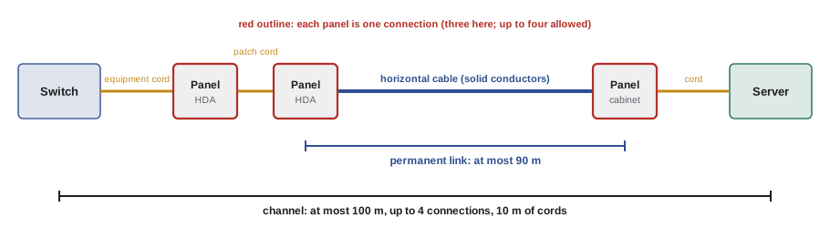
The limits matter because cords have higher loss per metre than solid-conductor horizontal cable. Their stranded conductors are more flexible but more lossy, so standards derate cord length: in TIA-568.2, the maximum horizontal cable length falls as cords get longer, about 1 m of horizontal for each 1.2 m to 1.5 m of extra cord, depending on the cord gauge.
Worked problem
How long can the horizontal cable be?
A designer wants 15 m of total cords at the ends of a Category 6A channel, using 24 AWG cords with a derating factor of 1.2 (each metre of cord counts as 1.2 m of horizontal cable). Given the 100 m channel model with 10 m of cords, how long can the horizontal cable be?
Show solution
- The model allows an equivalent of \(90 + 10 \times 1.2 = 102\) m.
- With 15 m of cords: \(15 \times 1.2 = 18\) m equivalent.
- Horizontal cable: \(102 - 18 = 84\) m.
Answer: About 84 m. In data centres links are usually far shorter, but long cords in large cross-connects and long runs to building systems at the edge of a site can reach these limits.
What a category guarantees
A category is a set of limits on transmission parameters, each specified as a curve against frequency up to the category's maximum frequency (250 MHz for Category 6, 500 MHz for Category 6A, 2,000 MHz for Category 8). Field testers measure every one of them on every pair or pair combination:
- Insertion loss (attenuation): the reduction in signal power along the pair, increasing with frequency and length. At 500 MHz, a 100 m Category 6A channel may lose about 49 dB, a reduction to roughly one hundred-thousandth of the power.
- Near-end crosstalk (NEXT): signal coupled from one pair into another, measured at the same end as the transmitter. It is worst at the near end, where the disturbing signal is strongest and the wanted signal from the far end weakest.
- Power-sum NEXT (PSNEXT): the combined crosstalk from all three other pairs into one pair, important because Gigabit and 10 Gigabit Ethernet transmit on all four pairs at once.
- Attenuation-to-crosstalk ratio (ACR-N and ACR-F): the margin between the wanted signal and the crosstalk at the near and far ends.
- Return loss: signal reflected back toward the transmitter by impedance changes, caused by poor terminations, kinks, crushed cable or mismatched components. Ethernet transceivers transmit and receive on the same pair at the same time, so reflections land directly on the receiver.
- Propagation delay and delay skew: how long the signal takes, and the difference between the fastest and slowest pairs.
- DC resistance and resistance unbalance: important for PoE, because unequal resistance in the two conductors of a pair creates a DC imbalance that can saturate the transformers in the equipment.
Each parameter is expressed in decibels relative to the limit, and a test result is reported as the worst-case margin, for example "PASS, worst NEXT margin 4.2 dB at 312 MHz".
Worked problem
Decibels and power
A channel has 32 dB insertion loss at 250 MHz, and crosstalk 40 dB below the transmitted signal (NEXT of 40 dB). What fraction of the transmitted power arrives at the far end, and what is the signal-to-crosstalk margin at the near end receiver?
Show solution
- Received power: \(10^{-32/10} = 6.3 \times 10^{-4}\), about 0.063% of transmitted.
- The received far-end signal is 32 dB below the transmit level; local crosstalk is 40 dB below it.
- Margin: \(40 - 32 = 8\) dB, so the wanted signal is \(10^{0.8} = 6.3\) times the crosstalk power.
Answer: About 0.063% of the power arrives, and the wanted signal is 8 dB (6.3 times) stronger than the near-end crosstalk. Digital signal processing in 10GBASE-T transceivers cancels most of the predictable crosstalk within the cable, so it can work with small margins like this; it cannot cancel crosstalk from other cables.
Alien crosstalk
Crosstalk from pairs within the same cable is predictable, because the transceiver knows what its own other pairs are transmitting, and 10GBASE-T uses echo and crosstalk cancellers to remove it. Crosstalk from pairs in neighbouring cables, called alien crosstalk, comes from signals the transceiver cannot know, so it cannot be cancelled and acts like noise.
Alien crosstalk was the main obstacle to 10GBASE-T on Category 6. Category 6A addresses it with larger cable diameters and spacers (in unshielded designs) or foil shields, and the standard sets limits for power-sum alien NEXT (PSANEXT) and alien far-end crosstalk. It is measured as a six-around-one test: one victim cable surrounded by six disturbers in a tight bundle, the worst case for a tray.
Practical consequences for design:
- Do not mix categories in a bundle: Category 6 cables bundled with 6A can raise alien crosstalk in the 6A links.
- Avoid combing large bundles so tightly that cables are crushed together over long distances; loosely laid cables in trays perform better than tightly cinched bundles.
- Use hook-and-loop ties, not tight plastic cable ties, which deform the cable and degrade return loss and crosstalk.
Shielding and bonding
Copper cables are classified by their shielding with a code of the form X/YTP, where X describes the overall screen and Y the shielding of individual pairs: U for none, F for foil, S for braid. Common data centre types are:
| Designation | Construction | Notes |
|---|---|---|
| U/UTP | Unshielded | Lightest and most flexible; Category 6A uses larger diameter to control alien crosstalk |
| F/UTP | Overall foil | Smaller diameter than unshielded 6A; very low alien crosstalk |
| U/FTP | Foil on each pair | Good pair isolation; common in Europe |
| S/FTP | Foil on each pair plus overall braid | Required for Category 7A (ISO) and common for Category 8.2 |
A shield only works if it is continuous through every connector and bonded at the patch panel to the telecommunications bonding system (TIA-607, Lesson 8). An unbonded or broken shield can act as an antenna, making interference worse. The shield is normally bonded at the panel end, and the equipment at the far end provides its own path through its chassis.
In practice, many data centres use U/UTP Category 6A for its lighter weight and simpler installation, and shielded cable where interference or bundle density demands it. Whichever is chosen, all components of the channel, cable, jacks, panels and cords, should come from one tested system, because the category is a property of the whole channel, not of any single part.
Field certification
Every copper link in a new plant is certified with a field tester meeting a defined accuracy level (Level IIIe for Category 6A, Level V for Category 8, under IEC 61935-1 and TIA-1152-A). The tester has a main unit and a remote unit with permanent-link or channel adapters, and it measures all the parameters above against the limits for the chosen category, as well as the wire map (each conductor connected to the right pin, with no shorts, opens, reversed or split pairs).
A split pair is a classic fault that simple continuity testers miss: the conductors are connected end to end, but two conductors from different pairs have been swapped, so the signal travels on wires that are not twisted together. It passes continuity but fails NEXT badly.
Results that pass by only a small margin are reported with an asterisk ("PASS*"), meaning the measurement is within the tester's accuracy of the limit; most specifications for new plant do not accept these as passes. Test results, with the link identifiers from the labelling scheme (Lesson 10), are saved and handed to the owner as part of the as-built record, and they support the manufacturer's warranty.
Common causes of failures
- Too much untwisting at the jack: each pair should stay twisted to within a few millimetres of the termination.
- Kinks, crushing or tight bends during pulling, which change the impedance and show up as return loss failures at a specific distance.
- Mixed components from different manufacturers or categories.
- Excessive length, which fails insertion loss.
- Wrong test limits or adapters selected on the tester, which produce false failures or false passes.
Power over Ethernet
PoE delivers DC power over the same twisted pairs that carry data, from the power sourcing equipment (PSE), usually a switch, to the powered device (PD). It uses the pairs in common mode: the voltage is applied between pairs, through centre taps of the transformers, so the data, which is differential, is unaffected. IEEE 802.3 defines four types:
| Type (standard) | Pairs | PSE output | Power at PD | Current per pair set |
|---|---|---|---|---|
| Type 1 (802.3af) | 2 | 15.4 W | 13.0 W | 350 mA |
| Type 2 (802.3at) | 2 | 30 W | 25.5 W | 600 mA |
| Type 3 (802.3bt) | 2 or 4 | 60 W | 51 W | 600 mA |
| Type 4 (802.3bt) | 4 | 90 W | 71.3 W | 866 mA |
The allowance for loss is set by the worst-case channel: 100 m of cable whose pair set (two conductors in parallel, out and back) has a loop resistance of 12.5 Ω.
Worked problem
Where the 90 W goes
A Type 4 PSE delivers 90 W over a 100 m channel with 12.5 Ω loop resistance per pair set and 866 mA in each of the two pair sets. How much power is lost in the cable, and how much reaches the device?
Show solution
- Loss per pair set: \(I^{2}R = 0.866^{2} \times 12.5 = 9.37\) W.
- Two pair sets: \(2 \times 9.37 = 18.7\) W.
- At the device: \(90 - 18.7 = 71.3\) W.
Answer: 18.7 W is lost in the cable, about 21%, and 71.3 W reaches the device, exactly the Type 4 PD figure. On a 30 m data centre link the loss is about 30% of that, and the PSE delivers less, since the PD draws only what it needs.
Heat in bundles
The power lost in the cable becomes heat. A single cable dissipates it easily, but in a bundle of a hundred cables the inner cables are surrounded by others that are also warming, and the temperature at the centre rises. If it exceeds the cable's rating (typically 60 °C or 75 °C), the cable ages faster and its insertion loss rises, which can cause data errors.
TIA TSB-184-A and ISO/IEC TS 29125 give guidance on bundle sizes and temperature rise for each cable type, typically limiting the rise to about 10 to 15 °C above ambient. Larger conductors (23 AWG in most Category 6A cables, compared with 24 AWG in many Category 6) and shielded constructions run cooler, and spreading cables in trays or using smaller bundles helps.
Worked problem
Heat in a PoE bundle
A bundle of 96 cables in a ceiling tray each carries Type 3 PoE at full current (600 mA per pair set, two pair sets) over 60 m. Pair-set loop resistance is proportional to length, 12.5 Ω at 100 m. Estimate the heat produced per metre of bundle.
Show solution
- Pair-set resistance at 60 m: \(12.5 \times 0.6 = 7.5\) Ω.
- Loss per cable: \(2 \times 0.6^{2} \times 7.5 = 5.4\) W over 60 m, or 0.09 W/m.
- Bundle: \(96 \times 0.09 = 8.6\) W per metre.
Answer: About 8.6 W per metre, comparable to a small heating cable, inside an insulated bundle. This is why designers break large PoE bundles into smaller groups and why codes limit current in large bundles.
Electrical codes also address PoE: the US National Electrical Code limits current per conductor in bundles of Class 2 and Class 3 data cables (Table 725.144) and recognizes limited-power (LP) cables rated for a stated current, and the Canadian Electrical Code has similar provisions. The data centre designer coordinates with the electrical engineer on these rules.
Where copper still belongs in a data centre
Even in facilities whose server and switch links are all fibre or twinax, copper remains the right medium for:
- Out-of-band management networks connecting every server's baseboard management controller, every switch console, PDU, UPS and cooling controller.
- Building systems: access control, cameras, environmental sensors, lighting controls, many of them PoE-powered.
- Wireless access points in offices and operations centres, where Category 6A supports multi-gigabit (2.5GBASE-T and 5GBASE-T) uplinks and high-power PoE.
- Short in-rack links where the equipment only offers RJ45 ports.
A common design provides each cabinet with a small number of Category 6A links to a management switch, separate from the high-speed fibre plant, along with a separate pathway or tray compartment for the copper.
Common mistakes
MistakeTreating the 100 m channel as a horizontal cable length.
InsteadThe permanent link is at most 90 m; cords use the remaining 10 m, and longer cords shorten the allowed horizontal run.
MistakeMixing manufacturers' jacks, panels and cords in a category channel.
InsteadUse one tested system, since the category belongs to the whole channel.
MistakeLeaving a shielded system's shield unbonded.
InsteadBond shields at the patch panel to the telecommunications bonding system.
MistakeCinching large bundles tightly with plastic ties.
InsteadLay cables loosely and use hook-and-loop ties to avoid crushing and alien crosstalk.
MistakeIgnoring heat in large PoE bundles.
InsteadFollow TSB-184-A bundle guidance and electrical code limits; split large bundles.
Summary and key terms
- The permanent link (90 m) is what the installer builds; the channel (100 m, four connections) adds cords.
- A category sets limits on insertion loss, NEXT, PSNEXT, ACR, return loss, delay and resistance unbalance.
- Alien crosstalk cannot be cancelled; Category 6A controls it with spacing or shielding.
- Shields must be continuous and bonded; all components should come from one system.
- Every link is certified with a field tester; marginal passes are not accepted.
- PoE Type 4 delivers 71.3 W after 18.7 W of worst-case cable loss; bundle heating limits density.
- Permanent link
- The installed cabling between two connection points, excluding cords.
- Channel
- The full end-to-end path including patch and equipment cords.
- Insertion loss
- The reduction of signal power along a link, in dB.
- NEXT
- Near-end crosstalk: signal coupled between pairs at the transmitting end.
- Return loss
- Signal reflected back by impedance mismatches.
- Alien crosstalk
- Crosstalk between pairs in different cables.
- Split pair
- A wiring fault that keeps continuity but splits signals across pairs.
- PSE
- Power sourcing equipment, usually a PoE switch.
- PD
- Powered device, such as an access point or camera.
- Pair set
- Two pairs used together as the out and return paths for PoE current.
Practice problems
Work each problem on paper first, then reveal the answer to check.
Maximum permanent link length and channel length in TIA-568.2?
Show answer
90 m and 100 m.
With 12 m of cords at derating 1.2, how long may the horizontal cable be?
Show answer
102 − 14.4 = 87.6 m.
What fraction of power remains after 20 dB of loss?
Show answer
1%.
Why can 10GBASE-T cancel internal crosstalk but not alien crosstalk?
Show answer
It knows the signals on its own pairs but not those in other cables.
What does the test configuration "six-around-one" measure?
Show answer
Alien crosstalk into one cable from six surrounding disturbers.
What does F/UTP mean?
Show answer
An overall foil screen with unshielded pairs.
Why does a split pair pass continuity but fail NEXT?
Show answer
The conductors connect end to end, but the signal travels on wires not twisted together.
Type 3 PoE loss at 100 m with 600 mA per pair set on two pair sets?
Show answer
2 × 0.6² × 12.5 = 9 W.
Type 4 loss on a 40 m channel?
Show answer
18.7 × 0.4 ≈ 7.5 W.
Name three uses of copper that remain in fibre-heavy data centres.
Show answer
Out-of-band management, building systems and cameras, wireless access points.
Lesson quiz · 5 questions
Score 60% or more to complete this lesson.
Create a free account to save your progress, take quizzes and earn a certificate.