
DCE-320 · Lesson 12 of 12 · 26 min
Delivering a cabling project: from requirements to handover
The earlier lessons covered the parts of a cabling plant one at a time: spaces and topology, media, copper performance, fibre physics, transceivers, high-density fibre, testing, pathways, AI clusters, cabinets and administration, and the outside plant. This final lesson puts them together in the sequence a real project follows, from the first requirements meeting to the handover of a documented, tested plant, and works through the main design calculations for a complete data hall. It also covers coordination with the other trades, quality control during installation, and the life of the plant after handover.
Project phases
Data centre cabling is designed and built as part of the larger facility project, and follows its phases:
- Requirements and concept: the owner's network architecture, cabinet counts, densities, redundancy level, growth plan and standards. The cabling designer turns these into a topology, space plan and media strategy.
- Design development: locations of every space (entrance rooms, MDA, HDAs), pathway routes and sizes, cabinet layouts, fibre counts and connector types, and coordination with structural, electrical, mechanical and fire protection designs.
- Construction documents: drawings, schedules and a specification precise enough for contractors to price and build without guessing.
- Tender and award: contractors price the work; the designer reviews bids and clarifies questions.
- Construction: submittals, installation, inspections, testing and correction of defects.
- Handover: as-built records, test results, warranty registration, training and operation and maintenance documents.
Cabling is often treated as a late, minor trade, but its pathways, spaces and power and cooling for network racks must be fixed early. A pathway that clashes with a cooling pipe found during construction costs far more to fix than one found in design.
Design deliverables
A complete cabling design package usually includes:
- A topology or riser diagram showing every space and the cabling between them, with fibre and copper counts.
- Floor plans with pathway routes, sizes and heights, cabinet positions with grid identifiers, and the locations of entrance facilities.
- Cabinet elevations for each cabinet type: panels, managers, PDUs and equipment positions.
- Schedules: trunk cables with identifiers, fibre counts, connector types and lengths; panel and cassette schedules; copper link schedules.
- Details: firestopping, bonding, tray supports, cabinet entry, building entrance.
- A specification: products (or performance requirements), installation methods, testing (Lesson 7), labelling (Lesson 10), submittals, warranty and acceptance.
Increasingly, the design is built as a 3D building information model (BIM), in which cable trays, busway, pipes and ducts can be checked for clashes automatically, and from which trunk lengths can be measured directly.
Worked design: a 160-cabinet data hall
The following example draws the main calculations together. An operator is fitting out a data hall for general-purpose cloud computing:
- 160 server cabinets in eight rows of twenty, 600 mm wide, at 10 kW each, with hot-aisle containment.
- A network row in the centre of the hall acting as the main distribution area, with spine and aggregation switches; leaf switches are top-of-rack in each server cabinet.
- Each server cabinet connects to the network row with two 144-fibre single-mode trunks (one to each of two redundant network cabinets), terminated in MPO-16 cassettes or panels at both ends.
- Each cabinet also needs two Category 6A links for out-of-band management.
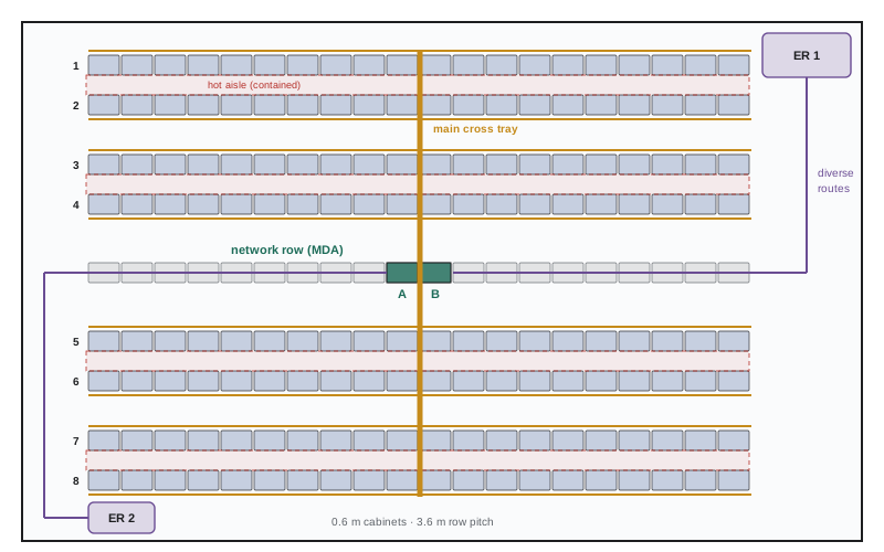
Step 1: Trunk lengths and quantities
Each trunk runs along its row's tray to the main cross tray, across to the network row, and down to the panels, plus slack. Because every cabinet is in a different position, trunk lengths vary; ordering them to length (rounded up to a standard increment) avoids large slack coils.
import math
from collections import Counter

# Trunk lengths and bill of materials for one data hall.
# Cabinets on a 0.6 m grid; network row (MDA/HDA) at the centre of the hall.
rows, cabs_per_row = 8, 20
cab_width, row_pitch = 0.6, 3.6       # metres: cabinet width, row-to-row spacing
mda_row = rows / 2 - 0.5              # network row sits between rows 4 and 5
mda_x = cabs_per_row * cab_width / 2  # network cabinets at mid-row
drops, slack = 2 * 2.5, 3.0           # down to the panels at each end, plus slack

lengths = Counter()
for r in range(rows):
    for c in range(cabs_per_row):
        x = (c + 0.5) * cab_width
        run = abs(x - mda_x) + abs(r - mda_row) * row_pitch + drops + slack
        lengths[5 * math.ceil(run / 5)] += 2      # two 144-fibre trunks per cabinet

total_trunks = sum(lengths.values())
total_m = sum(k * v for k, v in lengths.items())
print("trunk length  quantity")
for k in sorted(lengths):
    print(f"{k:8d} m  {lengths[k]:6d}")
print(f"trunks {total_trunks}, cable {total_m} m, fibres {total_trunks * 144}")
cassettes = total_trunks * 144 // 16 * 2         # MPO-16 cassettes at both ends
print(f"MPO-16 connections to terminate (both ends): {cassettes}")trunk length quantity
15 m 96
20 m 104
25 m 96
30 m 24
trunks 320, cable 6640 m, fibres 46080
MPO-16 connections to terminate (both ends): 5760The result: 320 trunks in four lengths, 6.6 km of cable and 46,080 fibres, with 5,760 MPO-16 connections to terminate or to buy pre-terminated. Pre-terminated, factory-tested trunks are the obvious choice at this scale, ordered from the schedule and labelled at the factory.
Step 2: Loss budget
Worked problem
Worst-case channel
The longest trunk is 30 m. A channel from a top-of-rack switch to a spine runs: cord, cassette in the server cabinet, trunk, cassette in the network cabinet, cord to the spine. Each cassette has an MPO on the trunk side and the channel passes through two mated MPO-APC connections (0.35 dB each maximum) plus two LC connections at the cassette fronts (0.25 dB each maximum). Fibre is 1.0 dB/km. Find the worst-case loss and the margin for 400GBASE-DR4 (3.0 dB) and 400GBASE-FR4 (4.0 dB).
Show solution
- Connections: \(2 \times 0.35 + 2 \times 0.25 = 1.20\) dB.
- Fibre: \(0.035 \times 1.0 = 0.035\) dB (30 m plus cords).
- Total: about 1.24 dB; margin 1.76 dB for DR4 and 2.76 dB for FR4.
Answer: About 1.24 dB worst case, comfortably within both budgets, with room for a future cross-connect. Note that DR4 uses MPO connectors end to end, so the LC cassette fronts would not be in its path; the calculation covers the worst combination the plant might see.
Step 3: Pathway sizing
Worked problem
Main cross tray fill
At the network row, all 320 trunks (11 mm diameter) converge in the main cross tray, along with the 320 Category 6A management links (7.5 mm) in a separate compartment. Size the fibre and copper compartments for 40% fill now, leaving room for growth.
Show solution
- Fibre area: \(320 \times \pi \times 5.5^{2} = 30{,}400\) mm²; at 40%: 76,000 mm², for example a 600 mm × 150 mm compartment (90,000 mm²).
- Copper area: \(320 \times \pi \times 3.75^{2} = 14{,}100\) mm²; at 40%: 35,300 mm², for example a 300 mm × 150 mm compartment (45,000 mm²).
Answer: A fibre compartment of about 600 × 150 mm and a copper compartment of about 300 × 150 mm. Along each row the trays carry only that row's 40 trunks and 40 copper links, so smaller trays suffice there.
Step 4: Redundancy and entrances
Each server cabinet has two trunks to two network cabinets on separate routes along the tray (or on trays on opposite sides of the row), so a single cut does not isolate it. Carriers enter through two entrance rooms at opposite corners of the building, with diverse conduit routes to the network row (Lesson 11). Network cabinets A and B are fed from separate power paths. Together these meet the redundancy requirements typical of a TIA-942 Rated-3 facility.
Step 5: Labelling and records
Every trunk, cassette, panel and port gets an identifier from the site scheme (Lesson 10), printed at the factory on the pre-terminated trunks. The schedule produced in Step 1 becomes the initial record in the DCIM system, and test results are attached to each link at acceptance.
Coordination with other trades
Cabling shares space with power, cooling and fire protection. Typical coordination points:
- Heights: overhead space is layered, for example lighting and sprinklers highest, then cable trays, then busway, with liquid-cooling pipes routed so that leaks cannot drip onto cabling.
- Separation from power: distances between data trays and power busway or cables, which depend on the shielding and the power circuits (Lesson 8).
- Supports: cable trays may share strut supports with other services only if the supports are designed for the combined load.
- Firestopping: every penetration of a fire-rated wall or floor needs a listed firestop system that can be reopened for new cables.
- Bonding: trays, cabinets and network equipment connect to the telecommunications bonding backbone and the building grounding electrode system.
- Cooling: blanking, cable entry seals and the location of network cabinets in the containment design.
Clash detection in a shared BIM model, and regular coordination meetings, catch most conflicts before installation.
Quality during installation
The specification sets the requirements; the construction phase checks they are met:
- Submittals: the contractor submits product data, certifications, test equipment calibration and installer qualifications for approval before ordering.
- Mock-up: one cabinet and a section of tray installed first and inspected, to agree the standard of workmanship.
- Inspections at key stages: pathways and supports before cable is pulled, firestopping before it is covered, cabinets after dressing.
- Testing as work proceeds, area by area, with results reviewed promptly so problems are not repeated.
- A deficiency list (punch list) of items to be corrected before acceptance.
Common defects found at inspection include exceeded bend radius at tray drops, crushed cables under ties, missing firestopping, missing labels or labels that do not match the records, unbonded trays and dirty connectors.
Handover and the life of the plant
At handover the owner receives as-built drawings, schedules, test results in native and summary form, warranty certificates, product data and maintenance guidance, and the DCIM records loaded and verified. A structured cabling warranty, typically 20 to 25 years from the manufacturer, usually requires installation by a certified installer and test results meeting the manufacturer's criteria.
The plant then lives through many changes:
- Daily moves, adds and changes under change control (Lesson 10).
- Equipment refreshes every three to five years, which may change optics and connector types, and ideally reuse the trunks.
- Expansions into new halls, connected through the backbone.
- Eventual decommissioning, when abandoned cables are removed and materials recovered. Copper and fibre cables, metal trays and cabinets can be recycled; sustainability reporting increasingly counts the embodied carbon of cabling materials as well as the energy of the equipment it connects.
A plant designed with clear topology, enough pathway space, single-mode fibre to every cabinet and good records will serve several generations of equipment. A plant without those will be rebuilt, at much higher cost, while the data centre is running.
Common mistakes
MistakeLeaving cabling pathway design until after mechanical and electrical layouts are fixed.
InsteadCoordinate pathways and network spaces from the concept stage.
MistakeOrdering all trunks at one length.
InsteadCalculate each length from the layout and round to standard increments.
MistakeAccepting the plant without verified records.
InsteadRequire as-builts, test results and DCIM records before acceptance.
MistakeSkipping the mock-up.
InsteadInstall and inspect a sample cabinet and tray section to agree workmanship first.
MistakeRouting cable trays below liquid-cooling pipes.
InsteadLayer services so leaks cannot drip onto cabling.
Summary and key terms
- Cabling follows the facility phases: requirements, design, documents, tender, construction and handover.
- Design deliverables include topology, plans, elevations, schedules, details and a specification.
- Trunk lengths, loss budgets and pathway fill are calculated from the layout.
- Redundant trunks, diverse routes and entrances meet the facility's rating.
- Coordination with other trades and staged inspections prevent costly rework.
- Handover delivers records, tests and warranty; the plant then lives through decades of change.
- Construction documents
- The drawings and specification from which contractors price and build.
- BIM
- Building information modelling: a shared 3D model of the facility.
- Clash detection
- Automatic finding of conflicts between services in a model.
- Schedule
- A table listing cables, panels or links with their properties.
- Submittal
- Product and qualification information submitted for approval.
- Mock-up
- A sample installation used to agree workmanship.
- Punch list
- A list of deficiencies to be corrected before acceptance.
- As-built records
- Drawings and data showing the plant as actually installed.
- Pre-terminated trunk
- A factory-terminated, tested multi-fibre cable.
- Decommissioning
- Removal of equipment and cabling at the end of its life.
Practice problems
Work each problem on paper first, then reveal the answer to check.
Name the six phases of a cabling project.
Show answer
Requirements, design development, construction documents, tender, construction, handover.
Why should pathways be coordinated early?
Show answer
Clashes found in construction cost far more to fix.
List four design deliverables.
Show answer
Topology diagram, floor plans, cabinet elevations, schedules (also details and specification).
A run of 17.4 m rounds to what length in 5 m steps?
Show answer
20 m.
Fibres in 50 trunks of 144 fibres?
Show answer
7,200.
Channel with four 0.35 dB connections and 50 m of fibre at 1.0 dB/km?
Show answer
1.45 dB.
Area of 100 cables of 10 mm diameter, and tray area at 40%?
Show answer
7,854 mm²; 19,600 mm².
What is a mock-up for?
Show answer
To agree the standard of workmanship before full installation.
What does a structured cabling warranty usually require?
Show answer
Certified installers and passing test results.
What should happen to abandoned cable at decommissioning?
Show answer
It should be removed and recycled.
Lesson quiz · 5 questions
Score 60% or more to complete this lesson.
Create a free account to save your progress, take quizzes and earn a certificate.