
DCE-310 · Lesson 8 of 12 · 31 min
Power quality, harmonics and ride-through
A data centre needs not just enough power but power of the right quality: the right voltage, at the right frequency, with a clean waveform and without interruptions. Lesson 1 noted that UPS systems protect the IT load from most disturbances and that data centres can disturb the grid in return. This lesson goes into detail. It classifies power quality disturbances, explains the voltage tolerance curves equipment is designed to, quantifies harmonics and their effects on transformers, neutrals and generators, examines voltage unbalance and power factor, and shows why the loads that are not on UPS, above all the cooling plant, decide whether a brief grid disturbance becomes a facility outage.
Kinds of disturbance
Power quality disturbances are classified (for example in IEEE 1159) by duration and magnitude:
- Transients: very short spikes or oscillations, microseconds to a few milliseconds, from lightning or switching capacitors and loads.
- Sags (dips) and swells: short reductions or increases in RMS voltage, half a cycle to a minute, mostly caused by faults elsewhere on the grid. Sags are by far the most common disturbance affecting industrial customers.
- Interruptions: loss of voltage, from momentary (a utility recloser operating, under a few seconds) to sustained.
- Long-duration variations: overvoltage or undervoltage lasting minutes or more.
- Waveform distortion: harmonics, interharmonics and notching from power electronics.
- Voltage unbalance and frequency variations.
A fault on a transmission line tens of kilometres away can cause a sag to 50% or 60% of normal voltage for 100 ms at a data centre, until the protective relays on that line clear it. Such events happen many times a year at most sites.
Voltage tolerance curves
The ITI (CBEMA) curve, published by the Information Technology Industry Council, describes the voltage disturbances that IT equipment should tolerate. Its main points, for 120 V equipment, are:
- Complete loss of voltage for up to 20 ms (about one cycle) with no interruption of function.
- Voltage as low as 70% for up to 0.5 s, and 80% for up to 10 s.
- Steady-state voltage within ±10% of nominal.
- Swells up to 120% for 0.5 s and 110% thereafter, with higher short transients.
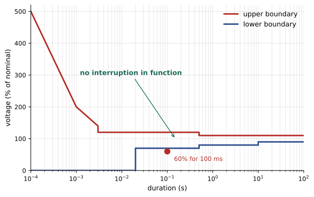
Modern server power supplies, with their internal hold-up capacitors (ELE-202, Lesson 10), usually do better than the curve. But the UPS makes the question moot for the IT load: a double-conversion UPS supplies the load from its batteries throughout any sag. The equipment that is exposed is everything not on UPS.
Worked problem
Is a sag a problem?
A transmission fault causes a sag to 60% of nominal voltage for 100 ms at a data centre. (a) Is this inside the ITI curve? (b) Does it affect the IT load? (c) What about the chillers, whose variable-speed drives trip if the DC bus falls below 80% for more than 50 ms?
Show solution
- (a) After 20 ms the curve requires tolerance only down to 70%; 60% for 100 ms falls below the curve.
- (b) The IT load is on UPS, which carries it from batteries: no effect.
- (c) The chiller drives trip. Restarting a large centrifugal chiller typically takes several minutes.
Answer: The sag lies outside the ITI curve, but the IT load is safe on its UPS. The chillers trip, and unless the cooling system has thermal storage, fast-restart chillers or drives with ride-through capability, temperatures in the data halls rise rapidly while they restart. Many facility outages blamed on "a power blip" are really cooling outages caused by mechanical loads that could not ride through.
Making mechanical loads ride through
Approaches include drives with ride-through settings that keep running at reduced speed or restart automatically ("flying restart"), feeding critical pumps, fans and controls from UPS (mechanical UPS), chilled-water or ice thermal storage that carries the cooling load for 10 to 20 minutes, and chillers with fast-restart features. The design should specify what disturbance the whole facility, not just the IT load, must ride through.
Harmonics
Electronic loads draw non-sinusoidal current. A non-sinusoidal periodic waveform can be expressed as a sum of sinusoids at the fundamental frequency (60 Hz) and its integer multiples, the harmonics (180 Hz is the 3rd, 300 Hz the 5th, and so on). The total harmonic distortion of a current is
and the RMS current, which is what heats conductors and transformers, is \(I_{rms} = I_{1}\sqrt{1 + THD_{I}^{2}}\).
Single-phase switch-mode power supplies without power factor correction draw strongly distorted current dominated by the 3rd harmonic. Three-phase rectifiers in UPS systems and drives produce mainly the 5th, 7th, 11th and 13th harmonics. Modern server supplies with active power factor correction draw nearly sinusoidal current at full load (current THD below 10%), but distortion rises at light load.
Worked problem
THD and RMS current
A panel feeding older IT equipment measures, per phase, a fundamental current of 100 A, a 3rd harmonic of 20 A, a 5th of 15 A and a 7th of 10 A. Find the current THD and the RMS current.
Show solution
- THD: \(\sqrt{20^{2} + 15^{2} + 10^{2}}/100 = \sqrt{725}/100 = 26.9\%\).
- RMS: \(100 \times \sqrt{1 + 0.269^{2}} = 103.6\) A.
Answer: A THD of about 27% and an RMS current of 103.6 A, 3.6% more than the fundamental alone. The extra heating is modest in the phase conductors but large in the neutral, where the 3rd harmonics add (Lesson 6), and in transformers, where harmonic currents cause disproportionate eddy-current losses.
Effects of harmonics
- Transformer heating: eddy-current losses rise roughly with the square of harmonic order. Transformers serving distorted loads are derated or specified with a K-factor rating, where \(K = \sum (I_{h}/I_{rms})^{2}h^{2}\). For the panel above, \(K \approx 2.2\), so a K-4 transformer would be suitable.
- Neutral overloading from triplen harmonics (Lesson 6).
- Voltage distortion: harmonic currents flowing through the source impedance distort the voltage seen by every other load, and can upset generators, drives and sensitive controls.
- Resonance: capacitors for power factor correction or filtering can resonate with the system inductance at a harmonic frequency, amplifying it dangerously.
- Generator problems: generators have higher impedance than the utility, so the same harmonic currents cause more voltage distortion when the site runs on generators.
Limits and mitigation
IEEE 519 sets limits for harmonics at the point of common coupling (PCC) with the utility. For systems up to 1 kV, voltage THD should not exceed 8%, and for 1 kV to 69 kV, 5%; current distortion limits depend on the ratio of the available short-circuit current to the load current, with stricter limits for large customers on weak systems. Mitigation options include active front-end UPS rectifiers and drives that draw near-sinusoidal current, passive tuned filters, active harmonic filters that inject cancelling currents, multi-pulse rectifiers with phase-shifting transformers, and choosing IT equipment with good power factor correction.
In Canada, utilities set harmonic and power quality requirements in their connection standards, generally based on IEEE 519 or the IEC 61000 series; Hydro-Québec, Hydro One and others publish their own technical requirements for large customers.
Voltage unbalance
In a three-phase system the three line voltages should be equal. Unbalance, caused by unequal single-phase loading or utility conditions, is expressed (in the NEMA definition) as the maximum deviation from the average line voltage divided by the average. Small voltage unbalance causes large current unbalance in motors and extra heating: as a rule of thumb, the percentage increase in motor temperature rise is about twice the square of the percentage voltage unbalance, and motors must be derated above 1% unbalance.
Worked problem
Calculating unbalance
The line voltages at a chiller are 416 V, 410 V and 419 V. Find the voltage unbalance and estimate the additional temperature rise in its motor.
Show solution
- Average: \((416 + 410 + 419)/3 = 415\) V.
- Maximum deviation: \(415 - 410 = 5\) V.
- Unbalance: \(5/415 = 1.2\%\).
- Temperature rise increase: \(2 \times 1.2^{2} \approx 2.9\%\).
Answer: About 1.2% unbalance, raising motor temperature rise by roughly 3%, tolerable but worth correcting. At 3% unbalance the increase would be about 18%, enough to shorten motor life seriously. Balancing single-phase loads across the phases in panels and PDUs is a routine part of operations.
Frequency, generators and grid ride-through settings
On the utility, frequency is held very close to 60 Hz by the whole interconnected grid. On generators it is not: when a large load is added or removed, the engine slows or speeds up until its governor responds, and the frequency can swing by several percent for a few seconds. Voltage also dips and recovers as the voltage regulator responds. Double-conversion UPS systems isolate the IT load from these swings, but they have input tolerances of their own: if frequency or voltage moves outside the UPS input window, the UPS transfers to battery, and if its bypass is not synchronized it cannot transfer to bypass safely. Generator and UPS settings must therefore be coordinated so that normal generator transients stay inside the UPS input window.
The same settings matter to the grid. When every UPS on a campus is set to transfer to battery at the slightest voltage dip, a single transmission fault can disconnect hundreds of megawatts of load at once (Lesson 2), and the sudden loss of load raises grid frequency and voltage. Grid operators increasingly ask large loads to specify their voltage and frequency ride-through behaviour, to avoid unnecessary transfers, and to reconnect gradually rather than all at once after a disturbance. Setting a UPS to ride through brief sags on its rectifier, where its design allows, and staging the return to utility power across a campus are simple, low-cost contributions to grid stability.
Worked problem
Frequency on a load step
A generator set can typically accept a load step of 40% of its rating with a frequency dip of up to 10%. A 2.5 MW generator carries 1.0 MW when a 1.2 MW chiller plant restarts all at once. Is the step acceptable, and what is a better approach?
Show solution
- Step: \(1.2/2.5 = 48\%\) of rating, above the 40% guideline.
- Expected frequency dip: more than 10%, i.e. below 54 Hz, which may push UPS inputs outside their window and trip other loads.
- Better: restart the chillers in stages, for example two steps of 0.6 MW (24% each) a few seconds apart.
Answer: The single 48% step is too large; staging the chiller restart keeps each step within the generator's capability. Load-add sequencing of this kind is built into the controls of the transfer and paralleling system (Lesson 10).
Power factor of IT loads
Lesson 1 discussed power factor and utility billing. Within the data centre, the IT load presents a special case: server power supplies with active power factor correction have a power factor near unity at full load, but their input filter capacitors draw a small leading (capacitive) current. At light load, when a facility is new and mostly empty, the IT load can present a leading power factor of 0.9 or lower. Most generators are rated for lagging power factor and can be pushed into unstable operation by significant leading load, because the leading current magnetizes the generator and its voltage regulator loses control. UPS systems with active front ends also present near-unity power factor to the generator. Designers check the generator's capability curve against the expected load power factor at all stages of build-out.
Measuring power quality
Power quality is measured with permanently installed meters at key points (service entrance, generator buses, UPS inputs and outputs) and with portable analysers for investigations. Class A instruments to IEC 61000-4-30 give comparable, traceable results. The measurements, recorded continuously with waveform capture of every event, let engineers correlate equipment trips with grid disturbances, verify harmonic compliance and understand how the facility behaves on generator. They feed the electrical power monitoring system (Lesson 10).
Common mistakes
MistakeAssuming the UPS protects the whole facility from sags.
InsteadCheck ride-through of chillers, pumps, fans and controls not on UPS.
MistakeSizing transformers for fundamental current only.
InsteadAccount for harmonic heating with a K-rating or derating.
MistakeAdding power factor capacitors without a resonance study.
InsteadCheck for harmonic resonance before installing capacitors.
MistakeIgnoring leading power factor at light IT load.
InsteadCheck generator capability for leading loads during early phases.
MistakeLeaving single-phase loads unbalanced across phases.
InsteadBalance loads to keep voltage unbalance below 1%.
Summary and key terms
- Disturbances include transients, sags, swells, interruptions, distortion, unbalance and frequency variation.
- The ITI (CBEMA) curve defines the voltage envelope IT equipment should tolerate.
- UPS protects IT loads; mechanical loads need their own ride-through or the site loses cooling.
- THD measures harmonic distortion; RMS current and transformer heating rise with it.
- IEEE 519 limits harmonics at the PCC; active front ends and filters reduce them.
- Voltage unbalance heats motors roughly in proportion to its square.
- Light IT loads can have a leading power factor that troubles generators.
- Sag (dip)
- A short reduction in RMS voltage.
- ITI (CBEMA) curve
- The voltage tolerance envelope for IT equipment.
- Ride-through
- The ability of equipment to keep operating through a disturbance.
- Harmonic
- A sinusoidal component at an integer multiple of the fundamental frequency.
- THD
- Total harmonic distortion: harmonic RMS divided by fundamental.
- K-factor
- A rating of a transformer's ability to carry harmonic current.
- PCC
- Point of common coupling, where the facility connects to the utility.
- Active front end
- A rectifier that draws near-sinusoidal current using controlled switching.
- Voltage unbalance
- Inequality of the three phase voltages.
- Leading power factor
- A power factor in which current leads voltage, as with capacitive loads.
Practice problems
Work each problem on paper first, then reveal the answer to check.
What disturbance most often affects industrial and data centre sites?
Show answer
Voltage sags from grid faults.
Per the ITI curve, how long must equipment ride through a complete loss of voltage?
Show answer
20 ms.
Is 75% voltage for 300 ms inside the ITI curve?
Show answer
Yes (above 70% for under 0.5 s).
Fundamental 50 A, 5th harmonic 10 A, 7th 5 A. THD?
Show answer
√125/50 = 22.4%.
RMS current for that waveform?
Show answer
50 × √1.05 = 51.2 A.
Voltage THD limit at a PCC below 1 kV per IEEE 519?
Show answer
8%.
Why is harmonic distortion worse on generator?
Show answer
Generators have higher impedance than the utility.
Voltages 480, 474, 486 V. Unbalance?
Show answer
6/480 = 1.25%.
Approximate motor temperature rise increase at 2% unbalance?
Show answer
About 8%.
Why can a lightly loaded new data hall trouble its generators?
Show answer
IT power supplies present a leading power factor at light load.
Lesson quiz · 5 questions
Score 60% or more to complete this lesson.
Create a free account to save your progress, take quizzes and earn a certificate.