
DCE-310 · Lesson 3 of 12 · 31 min
Medium-voltage switchgear and transformers
Between the substation and the data halls lies the medium-voltage (MV) system: the switchgear, cables and transformers that distribute power around the campus at a few tens of kilovolts and step it down to the low voltage used in the buildings. It is where most of the campus's redundancy is arranged, where the largest fault currents are handled, and where some of the longest-lead equipment sits. A typical large data hall is supplied by several MV feeders, each ending at a transformer that feeds one low-voltage switchboard and its UPS systems.
This chapter covers MV distribution arrangements, the construction and ratings of MV switchgear, the protective relays that guard it, and the transformers at its end: their ratings, impedance, connections, losses and the fault currents they allow.
Medium-voltage distribution arrangements
On a Canadian campus, MV distribution typically runs at 25 kV (or 27.6 kV or 13.8 kV, depending on the utility and province) from the main substation or utility service to transformers located next to each building or electrical room. Those transformers step down to 600Y/347 V, the standard Canadian low-voltage distribution system for commercial and industrial buildings.
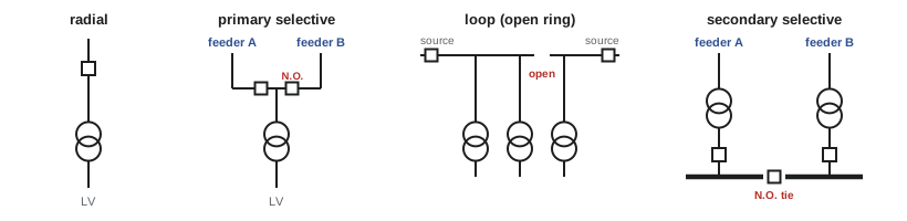
The way the MV feeders and transformers are connected decides how many failures the system can tolerate and whether maintenance requires an outage. Four arrangements are common:
- Radial: one MV feeder supplies each transformer. Simple and cheap, but a feeder failure leaves its transformers dead until repaired.
- Primary selective: each transformer can be fed from either of two MV feeders through two switches, one normally closed and one normally open. If the normal feeder fails, the transformer is switched to the alternate.
- Loop (open ring): feeders run from transformer to transformer in a loop fed from both ends, with one switch in the loop left open. A fault on a section of cable can be isolated and the rest of the loop fed from the other end. Loops built from compact ring main units are common on campuses.
- Secondary selective (double-ended): two transformers, fed from different MV sources, supply the two halves of a low-voltage switchboard joined by a normally open tie breaker. If one transformer or its feeder fails, the tie closes and the other transformer carries both halves. This is the low-voltage version of the main-tie-main arrangement from Lesson 1.
Many data centres go further and build fully separate A and B systems: two independent MV paths, each with its own transformers, switchboards and UPS systems, feeding the two power supplies of every server. This 2N architecture, and alternatives such as distributed redundant and block redundant designs that achieve similar availability with less equipment, are compared in DCE-340. Whatever the architecture, the MV system is where its first layer of redundancy lives.
Worked problem
How much can one MV feeder carry?
An MV feeder breaker and its cable are rated 1200 A. What power can the feeder carry at 25 kV and at 13.8 kV (assume a power factor of 0.95)?
Show solution
- At 25 kV: \(S = \sqrt{3} \times 25{,}000 \times 1200 = 52.0\) MVA, or \(52.0 \times 0.95 = 49.4\) MW.
- At 13.8 kV: \(S = \sqrt{3} \times 13{,}800 \times 1200 = 28.7\) MVA, or 27.3 MW.
Answer: About 49 MW at 25 kV but only 27 MW at 13.8 kV through the same 1200 A equipment. Higher MV voltages mean fewer feeders, breakers and cables for a large campus, which is why 25 kV (or higher, where the utility allows) is favoured.
Medium-voltage switchgear
MV switchgear is an assembly of breakers or switches, buses, instrument transformers, relays and controls in grounded metal enclosures. The main types are:
- Metal-clad switchgear: each breaker is a draw-out device in its own grounded compartment, with separate compartments for the bus, cables and controls, and automatic shutters that cover the live bus connections when a breaker is withdrawn. Modern MV breakers interrupt the arc in a vacuum bottle. Metal-clad gear is the standard for data centre MV distribution.
- Metal-enclosed switchgear: load-interrupter switches, often with fuses, in a common enclosure. Cheaper and simpler, used for transformer primaries and smaller systems.
- Ring main units: compact sealed units with two or three switches and a fused or breaker-protected transformer tee, used in loop systems. Many use SF₆ insulation, although SF₆-free designs using clean air or vacuum are now available.
Switchgear is specified by a set of ratings that must all suit the point in the system where it is installed:
- Rated maximum voltage (for example 15, 27 or 38 kV classes) and basic impulse insulation level (BIL), which sets its ability to withstand lightning and switching surges.
- Continuous current rating of the bus and of each breaker (commonly 1200, 2000 or 3000 A).
- Short-circuit interrupting and withstand ratings (for example 25, 31.5 or 40 kA), which must exceed the maximum fault current available at that point (Lesson 7).
Arc-resistant switchgear, tested to IEEE C37.20.7, is built to channel the hot gases and pressure of an internal arcing fault out through vents and plenums rather than through the front doors where a worker stands. It is widely specified for data centres because MV equipment must sometimes be operated while energized.
Protective relays
MV breakers do not trip on their own; they are tripped by protective relays fed from current and voltage transformers. Relay functions are identified by standard ANSI device numbers, which appear throughout one-line diagrams:
- 50 and 51: instantaneous and time overcurrent protection, the basic protection on every feeder.
- 50G/51G or 51N: ground (earth) fault overcurrent.
- 87: differential protection, which compares the current entering and leaving a zone (a transformer, a bus or a cable) and trips within a few cycles if they differ, meaning the fault is inside the zone.
- 27 and 59: undervoltage and overvoltage; 81: frequency; 86: lockout relay, which latches breakers open after a serious fault until a person investigates.
Modern relays are microprocessor-based, record the waveforms of every event, and communicate with the site's power monitoring system. Their settings come from the coordination study described in Lesson 7.
Distribution transformers
At the end of each MV feeder, a transformer steps the voltage down for the building. For data centres these "unit substation" transformers are typically 1500 to 3000 kVA (sometimes larger), close-coupled to a low-voltage switchboard, or pad-mounted outdoors with cables to an electrical room.
Construction and cooling
- Liquid-filled transformers have their core and windings immersed in insulating fluid, which cools and insulates. They are compact, efficient and long-lived. Mineral oil is flammable, so oil-filled units are usually installed outdoors with containment for spills and fire separation from buildings. Less-flammable natural ester fluids (made from vegetable oils) have much higher fire points and biodegrade, which eases siting.
- Dry-type transformers use air for cooling and solid insulation (vacuum-pressure impregnated or cast resin). They can be installed indoors with fewer fire precautions but are larger, noisier and somewhat less efficient. Fans can raise a dry-type unit's rating by roughly a third (an AA/FA rating).
The delta-wye connection
Most distribution transformers have a delta-connected primary and a wye-connected secondary. The wye secondary provides a neutral, so the low-voltage system can be solidly grounded and serve both three-phase and single-phase loads: line-to-line and line-to-neutral voltages are related by \(\sqrt{3}\), as in 600Y/347 V or 480Y/277 V. The delta primary traps triplen harmonic currents (the 3rd, 9th, 15th…) produced by single-phase electronic loads, so they circulate in the delta instead of flowing back into the MV system. A delta-wye transformer is a separately derived system: its secondary neutral is bonded to ground at the transformer, a requirement the codes treat in detail (Lesson 11).
Most transformers also have no-load taps on the primary, typically two steps of 2.5% above and below nominal, which allow the secondary voltage to be adjusted to match the actual utility voltage. They can only be changed with the transformer de-energized.
Impedance and fault current
A transformer's percent impedance (%Z) is the percentage of rated primary voltage that would drive full-load current through the secondary if it were short-circuited. It is stamped on the nameplate (around 5.75% is typical for a 2500 kVA unit) and has two important consequences. It sets the voltage drop under load, and it limits the current that flows into a short circuit on the secondary. Assuming the MV source can supply unlimited current (an "infinite bus", which gives a conservative, slightly high answer):
where \(Z_{\text{pu}}\) is the percent impedance as a decimal.
Worked problem
Full-load and fault current of a unit substation transformer
A 2500 kVA, 25 kV to 600Y/347 V transformer has an impedance of 5.75%. Find the primary and secondary full-load currents and the maximum fault current at the secondary terminals.
Show solution
- Primary: \(I = 2{,}500{,}000/(1.732 \times 25{,}000) = 57.7\) A.
- Secondary: \(I_{\text{FL}} = 2{,}500{,}000/(1.732 \times 600) = 2406\) A.
- Fault current: \(I_{\text{SC}} = 2406/0.0575 = 41{,}840\) A, about 42 kA.
Answer: About 58 A on the 25 kV side, 2406 A on the 600 V side, and up to about 42 kA of fault current at the secondary. Every breaker on that switchboard must be able to interrupt that current safely. A 3000 A main breaker and switchboard would typically be selected.
Impedance is a trade-off. A low-impedance transformer has better voltage regulation but allows higher fault currents, requiring more expensive breakers and raising arc flash energy. A high-impedance transformer limits fault current but its output voltage sags more under load. Designers choose impedance deliberately, sometimes specifying a non-standard value to keep fault currents within the rating of affordable low-voltage equipment.
Losses and efficiency
Transformer losses have two parts. No-load (core) losses come from magnetizing the steel core; they are present whenever the transformer is energized, whatever the load. Load (winding or copper) losses come from current in the windings and vary with the square of the load. Efficiency is highest at the load where the two are equal, usually around 35 to 50% of rating for distribution transformers.
Worked problem
Transformer losses at partial load
A 2500 kVA transformer has 3.5 kW of no-load loss and 20 kW of load loss at full load. Find the losses and efficiency at 60% load (unity power factor), and the load at which efficiency is highest.
Show solution
- At 60% load: \(P_{\text{loss}} = 3.5 + 20 \times 0.6^2 = 3.5 + 7.2 = 10.7\) kW.
- Output: \(0.6 \times 2500 = 1500\) kW. Efficiency: \(1500/(1500 + 10.7) = 99.29\%\).
- Peak efficiency when load loss equals no-load loss: \(20x^2 = 3.5\), so \(x = \sqrt{0.175} = 0.42\), or 42% load.
Answer: 10.7 kW of loss and 99.3% efficiency at 60% load; peak efficiency at about 42% load. In a 2N system each transformer normally runs below 50% load, close to its most efficient point. Over a year, 10.7 kW of continuous loss is about 94 MWh, which also becomes heat that must be removed if the transformer is indoors.
In Canada, the minimum efficiency of dry-type distribution transformers is set under federal Energy Efficiency Regulations administered by Natural Resources Canada, and many owners specify better-than-minimum units because the losses continue for decades.
Inrush and harmonics
When a transformer is first energized, its core can briefly saturate and draw an inrush current of 8 to 12 times full-load current for a few cycles. Protective relays and fuses must be set to ride through inrush while still tripping on genuine faults. Electronic loads also draw harmonic currents, which add heating in transformer windings. Modern server power supplies with active power factor correction draw fairly clean current, but older equipment and some UPS rectifiers produce significant harmonics, and transformers serving heavy non-linear loads are sometimes derated or specified with a K-factor rating that accounts for the extra heating.
Lead times and spares
In recent years, demand for transformers and switchgear from data centres, renewable energy projects and grid upgrades has far exceeded manufacturing capacity. Lead times for MV switchgear and distribution transformers have often stretched to a year or more, and for large power transformers to several years. Large operators now place framework orders years ahead, standardize equipment designs across many sites so that units are interchangeable, and hold strategic spares. For a design engineer, choosing standard ratings and confirming availability early can matter as much to the project schedule as any calculation.
Common mistakes
MistakeSelecting switchgear on voltage and continuous current alone.
InsteadThe interrupting and withstand ratings must exceed the available fault current at that location.
MistakeIgnoring transformer impedance when selecting downstream breakers.
InsteadLow impedance raises fault current; calculate \(I_{\text{SC}} \approx I_{\text{FL}}/Z\) before choosing equipment.
MistakeAssuming transformer losses scale linearly with load.
InsteadNo-load loss is constant; load loss varies with the square of load.
MistakeSetting transformer primary protection without allowing for inrush.
InsteadInrush of 8–12 times full-load current lasts a few cycles; protection must ride through it.
MistakePlacing mineral-oil transformers inside or close to buildings without precautions.
InsteadOil-filled units need separation, containment and fire protection; less-flammable fluids or dry types ease indoor siting.
Summary and key terms
- MV distribution carries campus power at tens of kilovolts to transformers near each building.
- Radial, primary selective, loop and secondary selective arrangements trade cost for the ability to survive failures; 2N designs add fully separate A and B paths.
- Metal-clad switchgear with draw-out vacuum breakers is standard; arc-resistant designs protect operators.
- Switchgear ratings: voltage and BIL, continuous current, and short-circuit interrupting and withstand.
- Relays (50/51 overcurrent, 87 differential, 27/59 voltage, 86 lockout) trip breakers; settings come from coordination studies.
- Delta-wye transformers provide a grounded neutral and trap triplen harmonics; taps adjust voltage.
- Secondary fault current \(\approx I_{\text{FL}}/Z\); impedance trades voltage regulation against fault level.
- Losses = constant no-load loss + load loss ∝ load²; efficiency peaks near 40% load; long lead times demand early ordering.
- Medium voltage
- Distribution voltages from about 1 kV to 35 kV (some codes now set the boundary at 1000 V AC).
- Primary selective
- An arrangement letting a transformer be fed from either of two MV feeders.
- Secondary selective
- A double-ended arrangement of two transformers feeding two low-voltage buses with a normally open tie.
- Ring main unit
- A compact switch assembly used in MV loop systems.
- Metal-clad switchgear
- Switchgear with draw-out breakers in separate grounded compartments.
- BIL
- Basic impulse insulation level: the surge voltage equipment insulation can withstand.
- Interrupting rating
- The highest fault current a device can safely interrupt.
- ANSI device number
- A standard number identifying a protective function, such as 51 for time overcurrent.
- Differential protection
- Protection that trips when current entering a zone differs from current leaving it.
- Unit substation
- A transformer close-coupled to MV switching and an LV switchboard.
- Percent impedance
- The percentage of rated voltage needed to drive full-load current through a short-circuited transformer.
- Separately derived system
- A system, such as a transformer secondary, with no direct conductor connection to the supply's conductors.
- No-load loss
- Constant transformer loss from magnetizing the core.
- Load loss
- Transformer winding loss that varies with the square of load current.
- Inrush current
- The brief high current drawn when a transformer is energized.
- K-factor
- A transformer rating for the extra heating caused by harmonic currents.
Practice problems
Work each problem on paper first, then reveal the answer to check.
What is the full-load secondary current of a 2000 kVA transformer at 600 V? At 480 V?
Show answer
2,000,000/(1.732 × 600) = 1925 A; at 480 V, 2406 A.
A 1500 kVA, 480 V transformer has 5.0% impedance. Estimate the maximum secondary fault current.
Show answer
I_FL = 1804 A; I_SC ≈ 1804/0.05 = 36.1 kA.
Why might a designer choose an 8% impedance transformer instead of 5.75%?
Show answer
To reduce available fault current (and arc flash energy) so less expensive breakers can be used, accepting more voltage drop under load.
How much power can a 2000 A MV feeder carry at 25 kV (pf 0.95)?
Show answer
1.732 × 25,000 × 2000 = 86.6 MVA, about 82 MW.
A transformer has 4 kW no-load loss and 24 kW full-load loss. Find the losses at 40% and 90% load.
Show answer
40%: 4 + 24 × 0.16 = 7.84 kW. 90%: 4 + 24 × 0.81 = 23.4 kW.
At what load is the transformer in the previous question most efficient?
Show answer
x = √(4/24) = 0.41, about 41% load.
What is the line-to-neutral voltage of a 600 V wye system, and of a 480 V wye system?
Show answer
600/1.732 = 347 V; 480/1.732 = 277 V.
What does an ANSI 87 relay do, and why is it fast?
Show answer
Differential protection compares currents into and out of a zone; any difference means a fault inside the zone, so it can trip immediately without waiting to coordinate with downstream devices.
A transformer has a full-load current of 105 A. What inrush might it draw on energization?
Show answer
About 8–12 times: roughly 840 to 1260 A for a few cycles.
Give two reasons data centres specify arc-resistant MV switchgear.
Show answer
It directs the energy of an internal arc away from operators, improving safety during switching; it limits damage and the risk of fire spread, reducing downtime.
Lesson quiz · 5 questions
Score 60% or more to complete this lesson.
Create a free account to save your progress, take quizzes and earn a certificate.