
DCE-310 · Lesson 1 of 12 · 34 min
Utility service and substations
Power is the first constraint on a modern data centre. A large campus can draw 100 to 1000 MW, comparable with a mid-sized city, and it draws that power around the clock with very little variation. Land, fibre and water can usually be found; a grid connection of hundreds of megawatts often cannot, at least not quickly. Power availability now decides where data centres are built, how fast they are built and how big they can grow.
DCE-200 traced the power chain from the transmission grid to the processor. This course designs it. It covers the electrical distribution of a data centre from the utility connection down to the rack, the calculations that size and protect it, and the codes that govern it. This first chapter starts at the top: how the grid delivers power, how a data centre connects to it, what is inside the substation that receives it, and how redundancy is built in from the very first breaker.
The grid in brief
Electricity is generated at power stations, typically at 13.8 to 25 kV, and immediately stepped up to transmission voltage. High voltage keeps the current, and therefore the \(I^2R\) losses, low over long distances. Transmission lines carry bulk power to substations near load centres, where transformers step it down to distribution voltages for delivery to customers.
In Canada, transmission voltages include 115, 138, 230 and 500 kV, and Hydro-Québec operates a 735 kV network to carry power from northern hydroelectric stations. Distribution is commonly at 25 kV or 12.5 kV in the west and Québec, and 27.6 kV or 13.8 kV in Ontario. Electricity is a provincial responsibility: each province has its own utilities and regulator, and in Ontario and Alberta an independent system operator (the IESO and AESO) runs the wholesale market and the grid.
Why does a data centre care about transmission voltage? Because the current for a given power falls in proportion to voltage, and the current sets the size of every conductor, breaker and transformer.
Worked problem
Current at different voltages
A 100 MW campus has a power factor of 0.95. Find the line current if it is supplied at 230 kV, at 138 kV and at 25 kV.
Show solution
- Three-phase current: \(I = P/(\sqrt{3}\,V_L\,\text{pf})\).
- 230 kV: \(I = 100 \times 10^6/(1.732 \times 230{,}000 \times 0.95) = 264\) A.
- 138 kV: 440 A.
- 25 kV: 2431 A.
Answer: 264 A at 230 kV, 440 A at 138 kV and about 2400 A at 25 kV. A single 25 kV distribution feeder typically carries only a few hundred amperes, so a 100 MW load at distribution voltage would need many feeders. Large campuses therefore connect at transmission voltage and build their own substation.
Service options
How a data centre connects depends mostly on its size.
- Low-voltage service: small server rooms and edge sites take power from a utility pad-mounted transformer at the same voltage as any commercial building.
- Medium-voltage (distribution) service: facilities up to roughly 10 to 30 MW are typically fed by one or more utility distribution feeders. The owner receives power at medium voltage and owns the switchgear and transformers that step it down.
- Transmission-level service: large facilities connect directly to the transmission network. Either the utility builds a dedicated substation next to the campus, or the owner builds and operates its own high-voltage substation. The point where ownership changes, the point of interconnection, is defined in the interconnection agreement.
Whatever the level, the utility will study the request before agreeing to it: whether the transmission lines and existing substations can carry the extra load, what upgrades are needed and who pays. For large loads these studies and upgrades can take years, which is why DCE-420 treats power procurement and interconnection as a project in its own right. A frequent strategy is to start a campus on a smaller interim supply while the full transmission connection is built.
Dual utility feeds
A single utility line is a single point of failure. Data centre owners therefore ask for two independent supplies, ideally from two different utility substations over separate routes, so that a fault on one line or one substation leaves the other in service. Utilities cannot always provide true independence: two feeders from the same substation still share that substation. The owner must understand exactly how independent the feeds are, the same shared-risk reasoning used for fibre routes in DCE-210. Generators and UPS systems (DCE-340) remain essential whatever the utility arrangement, because even two utility feeds can fail together during a wide-area disturbance.
Inside a substation
A substation switches, transforms, measures and protects. The main components of a customer-owned high-voltage substation are:
- Line entrances with disconnect switches, which provide visible isolation of each incoming line for maintenance.
- Circuit breakers, which interrupt current, including fault currents of tens of kiloamperes. High-voltage breakers use sulphur hexafluoride (SF₆) gas or vacuum to extinguish the arc; because SF₆ is an extremely potent greenhouse gas, SF₆-free designs are increasingly specified.
- Power transformers, which step transmission voltage down to the site's medium distribution voltage. They are rated in MVA and are usually oil-filled, with cooling classes such as ONAN (oil natural, air natural) and ONAF (oil natural, air forced), which add fans to raise the rating.
- Instrument transformers: current transformers (CTs) and voltage transformers (VTs or PTs) that scale currents and voltages down to safe levels for meters and relays.
- Protective relays, microprocessor devices that watch those signals and trip breakers within cycles when they detect a fault.
- Surge arresters to protect equipment from lightning and switching surges, a ground grid of buried conductors to limit dangerous step and touch voltages during faults, and a control building with batteries, communications and the protection and control panels.
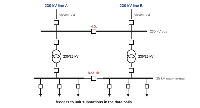
Electrical engineers describe these systems with one-line (single-line) diagrams, which represent each three-phase circuit with a single line and each device with a standard symbol. The one-line diagram is the master document of any electrical design, from which equipment is specified, protection is studied and operators plan switching.
Bus configurations
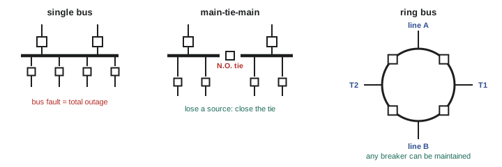
The arrangement of breakers and buses decides how well the substation survives failures and maintenance. The common configurations, in rising order of cost and reliability, are:
- Single bus: all lines and transformers connect to one bus. Simple and cheap, but a bus fault or bus maintenance takes everything out.
- Main-tie-main (split bus): two buses, each fed by its own source, joined by a normally open tie breaker. If one source fails, the tie closes and the other source carries both buses. This is the workhorse of medium-voltage data centre distribution.
- Ring bus: breakers arranged in a loop, with each line or transformer connected between two breakers. Any breaker can be taken out for maintenance without interrupting a circuit.
- Breaker-and-a-half: two buses with three breakers for every two circuits. Very reliable and flexible, common at large transmission substations.
Sizing and redundancy of substation transformers
Substation transformers are large, expensive and slow to replace: lead times for large power transformers have stretched to two to four years in recent years, and a failed unit cannot be swapped quickly. They are therefore always installed with redundancy, so that the full load can be carried with one transformer out of service.
Worked problem
Transformer redundancy
A campus will draw 150 MW at a power factor of 0.95. Compare an N+1 design using 60 MVA transformers with a 2N design.
Show solution
- Apparent power: \(S = 150/0.95 = 158\) MVA.
- N+1: with one unit out, the rest must carry 158 MVA. Three 60 MVA units give 180 MVA, so N = 3 and four units are installed (240 MVA in total).
- Normal loading with four in service: \(158/240 = 66\%\) each; with one out, \(158/180 = 88\%\) each.
- 2N: two transformers, each able to carry the whole load alone, so each must be at least 158 MVA; with fan cooling, two 160 MVA units would do. Normally each carries 79 MVA, or 49%.
Answer: N+1 needs four 60 MVA transformers (240 MVA installed); 2N needs two of about 160 MVA (320 MVA installed). N+1 installs less capacity, while 2N gives two fully independent paths. Large campuses often use N+1 at the substation and add independence lower down.
Transformers can carry more than their nameplate rating for limited periods, depending on cooling and the temperature of the oil and windings, which is one way the "one out of service" case is handled. Standards for transformer loading (IEEE C57.91 and IEC 60076-7) let engineers calculate how long a given overload can be sustained without excessive ageing of the insulation.
Power factor, metering and the bill
A utility measures both energy (kWh) and peak demand (kW, usually the highest 15- or 30-minute average in a month), and large customers often pay separately for each. Utilities also care about reactive power: a load with a low power factor draws more current, and therefore uses more transformer and line capacity, for the same real power. Many tariffs penalize power factors below about 0.9 to 0.95.
Modern servers have power supplies with active power factor correction, so IT load typically runs at a power factor of 0.95 to 0.99. Large motor loads, such as chillers and pumps, and lightly loaded transformers lower it. In AI campuses with fluctuating loads, the power factor and the voltage stability of the connection are studied carefully.
Worked problem
The value of power factor correction
A site draws 80 MW at a power factor of 0.90. How much apparent power does it draw, and how much reactive power must be supplied by capacitor banks or other correction to raise the power factor to 0.98?
Show solution
- At 0.90: \(S = 80/0.90 = 88.9\) MVA; \(Q = P\tan(\cos^{-1}0.90) = 80 \times 0.484 = 38.7\) Mvar.
- At 0.98: \(S = 80/0.98 = 81.6\) MVA; \(Q = 80 \times 0.203 = 16.2\) Mvar.
- Correction needed: \(38.7 - 16.2 = 22.5\) Mvar.
Answer: About 22.5 Mvar of correction reduces the apparent power from 88.9 to 81.6 MVA, freeing about 7 MVA of transformer and line capacity and avoiding power factor penalties.
Worked problem
Energy and demand on the bill
In a 30-day month a site averages 60 MW, with a peak 15-minute demand of 64 MW. The tariff is $0.06 per kWh and $10 per kW of peak demand per month (illustrative prices). Estimate the bill.
Show solution
- Energy: \(60 \text{ MW} \times 720 \text{ h} = 43{,}200\) MWh = 43.2 million kWh.
- Energy charge: \(43.2 \times 10^6 \times 0.06 = \$2.59\) million.
- Demand charge: \(64{,}000 \text{ kW} \times \$10 = \$640{,}000\).
- Total: about $3.23 million for the month.
Answer: About $3.2 million, of which roughly 80% is energy. Because data centres run at a high, steady load factor, their demand charges are small relative to energy, and every point of PUE improvement shows up directly in the energy charge.
Power quality and grid interaction
Data centre electronics are protected from short disturbances by their UPS systems, so momentary voltage sags, which are common on any grid during lightning and faults, rarely affect the IT load. They do affect the grid, however. When a sag makes many data centres transfer to their UPS batteries and generators at the same moment, a large block of load disappears from the grid in seconds and returns later. In July 2024, a transmission fault in Northern Virginia caused about 1,500 MW of data centre load to drop off the grid at once, an event studied closely by NERC, the North American Electric Reliability Corporation, whose standards cover both Canada and the United States. Grid operators now increasingly ask large loads to ride through disturbances and to coordinate how they disconnect and reconnect. Lesson 8 examines power quality in detail.
The data centre, in turn, can disturb the grid. The power electronics in UPS systems and server supplies draw harmonic currents; very large AI training clusters can swing their power by tens of megawatts in seconds as jobs start, stop and synchronize; and large motor starts cause voltage dips. Interconnection studies examine these effects, and utilities may require harmonic filters, staged ramping, or energy storage to smooth the load seen by the grid.
How this course is organized
The course follows power from the grid to the rack and through the life of the facility:
- Lesson 2 estimates the load that everything else must serve.
- Lessons 3 and 4 cover the medium-voltage system: switchgear and transformers, then cables, duct banks and system grounding.
- Lessons 5 and 6 cover low-voltage distribution: switchboards, busway and PDUs, then conductors, raceways and circuit sizing.
- Lesson 7 covers short circuits, coordination and arc flash, Lesson 8 power quality and ride-through, and Lesson 9 grounding, bonding, lightning and surge protection.
- Lesson 10 covers metering, monitoring and control, Lesson 11 the electrical code and workplace safety rules, and Lesson 12 design deliverables, maintenance and the future of data centre power.
Common mistakes
MistakeAssuming two utility feeders are independent because they arrive on two cables.
InsteadTrace both back to their sources; feeders from the same substation or on the same route share failure modes.
MistakeSizing transformers on MW instead of MVA.
InsteadTransformers carry apparent power: divide real power by power factor.
MistakeSizing N+1 transformers so the total installed equals the load.
InsteadThe load must be carried with one unit out of service; size the remaining units for the full load.
MistakeLeaving the utility connection until late in the project.
InsteadInterconnection studies, upgrades and transformer lead times can take years; start in site selection.
MistakeTreating grid disturbances as only the data centre's problem.
InsteadLarge loads affect the grid too; ride-through, ramp rates and harmonics are part of the interconnection.
Summary and key terms
- Power availability now governs where and how fast large data centres are built.
- High transmission voltages keep current low: 100 MW at 230 kV is only about 260 A.
- Small sites take low- or medium-voltage service; large campuses connect at transmission voltage with their own or a dedicated substation.
- Dual feeds help only if they are truly independent; generators and UPS remain essential.
- Substations contain disconnects, breakers, power and instrument transformers, relays, arresters, a ground grid and a control building.
- Bus arrangements range from single bus to main-tie-main, ring bus and breaker-and-a-half, trading cost for reliability.
- Transformers are sized in MVA with N+1 or 2N redundancy; long lead times make spares and early ordering important.
- Bills charge for energy and peak demand; power factor correction frees capacity; large loads must ride through grid disturbances.
- Transmission
- High-voltage lines carrying bulk power between generating stations and substations.
- Distribution
- Medium-voltage networks delivering power from substations to customers.
- Point of interconnection
- The location where the customer's facilities connect to the utility system.
- Substation
- A facility that switches, transforms, measures and protects power circuits.
- One-line diagram
- A diagram representing three-phase circuits with single lines and standard symbols.
- Circuit breaker
- A switching device that can interrupt normal and fault currents.
- Disconnect switch
- A switch providing visible isolation of a circuit, not intended to interrupt load or fault current.
- Instrument transformer
- A current or voltage transformer that scales quantities down for meters and relays.
- Protective relay
- A device that detects abnormal conditions and trips breakers.
- Main-tie-main
- Two buses, each with its own source, joined by a normally open tie breaker.
- Ring bus
- A substation arrangement with breakers in a closed loop.
- MVA
- Megavolt-amperes: the unit of apparent power used to rate large transformers.
- Power factor
- The ratio of real power to apparent power.
- Demand charge
- A charge based on the highest average power drawn over a short interval in a billing period.
- Ride-through
- The ability of a load or generator to stay connected through a short grid disturbance.
Practice problems
Work each problem on paper first, then reveal the answer to check.
Find the current drawn by a 40 MW load at 0.97 power factor supplied at 138 kV.
Show answer
I = 40 × 10⁶/(1.732 × 138,000 × 0.97) = 172.5 A.
A 30 MW load at 0.95 pf is fed at 13.8 kV. What current flows, and how many 600 A feeders would be needed?
Show answer
I = 30 × 10⁶/(1.732 × 13,800 × 0.95) = 1321 A; at least three 600 A feeders (more for redundancy).
What apparent power does a 90 MW load at power factor 0.92 draw?
Show answer
90/0.92 = 97.8 MVA.
A 200 MVA load is supplied by N+1 transformers of 80 MVA. How many are needed?
Show answer
With one out, the rest must supply 200 MVA: 3 × 80 = 240 ≥ 200, so N = 3 and four are installed.
Four transformers of 50 MVA serve 130 MVA. What is each one's loading normally and with one out of service?
Show answer
Normally 130/200 = 65%; with one out 130/150 = 87%.
How much reactive power must be compensated to raise a 50 MW load from pf 0.88 to 0.97?
Show answer
Q₁ = 50 tan(cos⁻¹ 0.88) = 27.0 Mvar; Q₂ = 50 tan(cos⁻¹ 0.97) = 12.5 Mvar; about 14.5 Mvar.
Why does a main-tie-main arrangement use a normally open tie breaker?
Show answer
Keeping the tie open separates the two sources, so a fault on one side does not affect the other, and limits fault current. The tie closes only when one source is lost, so one source can carry both buses.
A site averages 25 MW for a 31-day month. At $0.07 per kWh, what is the energy charge?
Show answer
25 MW × 744 h = 18,600 MWh; × $70/MWh = $1.30 million.
List four main components of a high-voltage customer substation and their purposes.
Show answer
Any four: disconnect switches (isolation), circuit breakers (interrupt faults), power transformers (step down voltage), CTs and VTs (measurement), protective relays (detect faults and trip), surge arresters (overvoltage protection), ground grid (limit step and touch voltage), control building (control, batteries, communications).
Why might a utility ask a large data centre to ride through voltage sags rather than transfer to backup power?
Show answer
Many sites transferring at once removes a large block of load suddenly, which can disturb grid frequency and voltage; riding through keeps the load steady and the grid stable.
Lesson quiz · 5 questions
Score 60% or more to complete this lesson.
Create a free account to save your progress, take quizzes and earn a certificate.