
DCE-310 · Lesson 5 of 12 · 32 min
Low-voltage switchboards, busway and PDUs
Below the transformer, power enters the low-voltage (LV) system: everything under 1000 V. This is where the data centre's electrical design becomes most visible and most dense. Large switchboards line the electrical rooms, UPS systems sit beside them, and power fans out through PDUs, panelboards and overhead busways to thousands of rack circuits. Most of the equipment an operator works on day to day is here, and so are most of the design decisions that decide how much IT load each rack can actually use.
This chapter follows the LV chain from the transformer secondary to the rack: switchboards and the breakers in them, transfer switches and UPS boards, PDUs and remote power panels, overhead busway, rack PDUs, and the choice between 208 V and 415 V distribution. It ends with how A and B power paths are loaded and how capacity becomes stranded.
The low-voltage chain
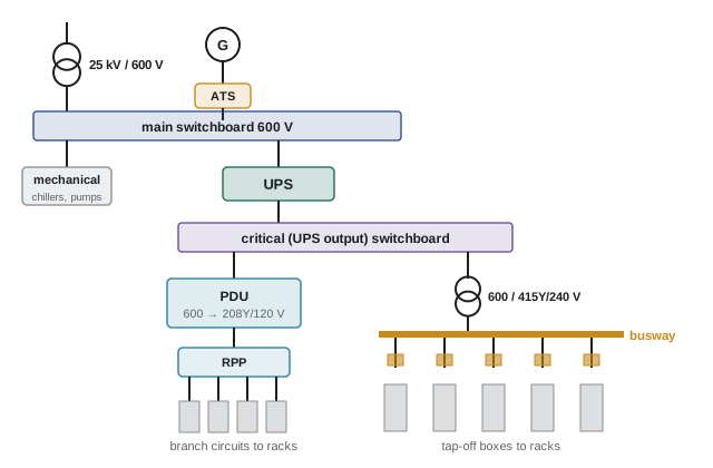
In a typical Canadian design, the transformer secondary at 600Y/347 V feeds a main switchboard, which also connects to the standby generator through an automatic transfer switch or paralleling switchgear. The main switchboard feeds the UPS systems and the mechanical loads (chillers, pumps, air handlers), which are backed by generators but usually not by the UPS. The UPS output feeds a critical distribution switchboard, and from there power is stepped down to 208Y/120 V or 415Y/240 V for the IT equipment.
Switchboards, switchgear and breakers
Low-voltage assemblies come in two main classes, built to different standards:
- Switchboards (certified to CSA C22.2 No. 244 in Canada) are compact assemblies, usually with fixed-mounted breakers. They are economical and common for most distribution.
- Low-voltage switchgear (certified to CSA C22.2 No. 31) uses draw-out power circuit breakers in separate compartments and is tested to withstand fault current for longer, which makes selective coordination easier (Lesson 7). It is preferred for main and critical distribution where maintainability and selectivity matter most.
The breakers in these assemblies fall into three families. Molded-case circuit breakers (MCCBs) are sealed units used for feeders and branch circuits. Insulated-case breakers are larger, often draw-out, used for mains and large feeders. Low-voltage power circuit breakers are the heavy-duty draw-out type used in switchgear. Larger breakers have electronic trip units with adjustable settings, usually described by the letters LSIG: long-time (overload), short-time (moderate faults, with a delay for coordination), instantaneous (heavy faults) and ground fault.
Breakers are either standard (80%) rated or 100% rated. A standard-rated breaker may carry continuous load (three hours or more, which describes all data centre IT load) only up to 80% of its rating. A 100%-rated breaker, tested in its assembly for continuous full-load operation, can carry 100%. Because IT load is continuous by nature, this distinction appears in every sizing calculation.
Transfer switches and bypasses
An automatic transfer switch (ATS) moves a load between the utility and a generator source. When utility voltage fails, the ATS signals the generator to start, waits for it to reach stable voltage and frequency (typically under 10 to 15 seconds), and transfers the load. When the utility returns and is stable, it transfers back, usually after a delay. Large sites use paralleling switchgear instead, which synchronizes many generators onto a common bus. ATSs for critical loads often come with a bypass-isolation switch so the ATS itself can be maintained without an outage. Similarly, every UPS has a maintenance bypass, an arrangement of breakers that routes power around the UPS so it can be serviced while the load stays on (raw utility or generator) power. Lesson 11 and DCE-340 discuss these further.
PDUs and remote power panels
The traditional way to deliver power to racks is through power distribution units (PDUs) on the data hall floor. A floor-standing PDU contains a step-down transformer, typically 150 to 300 kVA, and one or more panelboards with dozens of branch circuit breakers. Each breaker feeds a cable (overhead or under a raised floor) to a receptacle at a rack. Remote power panels (RPPs) are cabinets containing extra panelboards, without transformers, fed from a PDU and placed closer to the racks to shorten branch circuits and add circuit capacity.
In Canada, the PDU transformer steps 600 V down to 208Y/120 V. Each PDU transformer is a separately derived system with its own neutral-to-ground bond, so it also provides a local, clean grounding reference for the IT equipment.
Worked problem
PDU currents
A 225 kVA PDU transformer steps 600 V down to 208 V. Find its primary and secondary full-load currents.
Show solution
- Primary: \(225{,}000/(1.732 \times 600) = 217\) A.
- Secondary: \(225{,}000/(1.732 \times 208) = 625\) A.
Answer: 217 A in and 625 A out. The low-voltage side carries almost three times the current of the 600 V side, which is why the step-down is placed as close to the racks as possible: the long runs are at 600 V and only the short final circuits are at 208 V.
Overhead busway
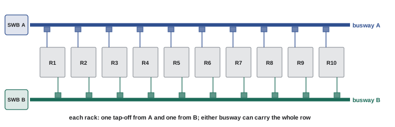
Many modern data halls replace PDU branch cabling with overhead busway: a prefabricated enclosed track of copper or aluminium busbars running above each row of racks. Plug-in tap-off boxes, each containing a breaker and a cable or receptacle for one rack, can be added, removed or moved without shutting the busway down. Busway is fed at one end (or the middle) from a switchboard or transformer. Its advantages are flexibility (racks can be added or changed in minutes), speed of installation, and the elimination of hundreds of individual branch cables under the floor or in trays. Its disadvantages are a higher cost at low densities and the need to plan tap-off ratings and phase balance carefully.
Worked problem
Sizing a row busway
A row has 20 racks of 15 kW each, fed at 415 V three-phase with a power factor of 0.95. Each rack is dual-corded, with an A busway and a B busway along the row. What current must each busway be able to carry, and what busway rating would you choose?
Show solution
- Row load: \(20 \times 15 = 300\) kW.
- If one busway fails, the other must carry the entire row: \(I = 300{,}000/(1.732 \times 415 \times 0.95) = 439\) A.
- IT load is continuous. With standard-rated overcurrent protection, the busway and its feeder breaker must be rated at least \(439/0.8 = 549\) A.
- Choose the next standard size, for example 600 or 630 A, or 800 A to allow for future growth in rack density.
Answer: Each busway must carry 439 A alone, so it needs a rating of at least 549 A; a 630 A or 800 A busway would be selected. In normal operation each busway carries only about half the row, around 220 A.
Voltage drop along a busway is usually small because the bars are large and the run short, but it should still be checked for long rows. Phase balance matters too: tap-off boxes are distributed across the three phases so that each phase carries a similar share.
208 V or 415 V?
For decades, North American data centres delivered IT power at 208Y/120 V through PDU transformers, because that is the standard North American commercial voltage. Today many new designs distribute at 415Y/240 V instead. In Canada the 600 V system is stepped down to 415Y/240 V by a transformer at the switchboard or busway feed, and the busway or panelboards then carry 415 V all the way to the racks.
The case for 415Y/240 V is strong:
- Server power supplies accept 200 to 240 V. On a 415Y/240 V system, each power supply is connected line to neutral at 240 V, which is near the top of its range and its most efficient operating point.
- The same current carries twice as much power: a 415 V circuit delivers 2.0 times the power of a 208 V circuit of the same ampere rating, so rack circuits, connectors and cables shrink.
- It removes a stage of transformation close to the racks (the PDU transformer), saving roughly 1 to 2% of losses and the floor space and heat of PDU transformers.
The trade-offs are higher available fault current at the racks, which raises interrupting ratings and arc flash energy, and the fact that 415Y/240 V equipment (panelboards, breakers, receptacles) must be suitable for that voltage. 415 V is also the standard voltage in much of the world, so equipment is readily available.
| Rack circuit (three-phase) | Breaker rating | Continuous capacity (80%) |
|---|---|---|
| 208 V | 30 A | 8.6 kW |
| 208 V | 60 A | 17.3 kW |
| 415 V | 30 A | 17.3 kW |
| 415 V | 60 A | 34.5 kW |
Rack PDUs
Inside the rack, power strips called rack PDUs distribute power to each server. A typical rack has two (A and B), each fed from its own circuit, mounted vertically at the back of the rack. Common types are basic (power distribution only), metered (showing total current, so operators can see loading), monitored per outlet, and switched (allowing remote power cycling of individual outlets). Outlets are usually IEC 60320 C13 (up to about 10 to 15 A) and C19 (up to about 16 to 20 A) types; inputs use locking or industrial connectors such as NEMA L-series or IEC 60309 "pin and sleeve" plugs. A three-phase rack PDU arranges its outlets in groups across the phases, and keeping those groups balanced keeps the upstream circuit balanced.
A and B paths and stranded capacity
Almost every server has two power supplies, each plugged into a different rack PDU fed from a different path. In normal operation the two supplies share the load roughly equally; if one path fails, the other must carry the whole load. This has a profound effect on how much of the installed capacity can actually be used.
Worked problem
Loading a dual-fed rack
A rack draws 12 kW and is fed by one A circuit and one B circuit. (a) What does each circuit carry normally and after a failure? (b) Is a 208 V, 30 A three-phase circuit adequate? (c) Is a 415 V, 30 A three-phase circuit adequate?
Show solution
- (a) Normally about 6 kW per circuit; after a failure, the surviving circuit carries all 12 kW.
- (b) A 208 V, 30 A circuit can carry 8.6 kW continuously. It is fine normally (6 kW) but overloads after a failure (12 kW). Not adequate: each side would need a 60 A circuit (17.3 kW) or two 30 A circuits.
- (c) A 415 V, 30 A circuit carries 17.3 kW continuously: adequate on its own after a failure.
Answer: Each circuit must be sized for the full rack load, even though it normally carries half. The 415 V, 30 A circuit is sufficient; at 208 V the rack needs 60 A circuits or more circuits per side.
The same logic applies all the way up the chain. In a 2N system, every UPS, switchboard and transformer normally runs below 50% of its rating, because its partner may need to hand over its whole load. If loads are not balanced between paths, or if some racks draw far less than the capacity reserved for them, capacity that has been built and paid for cannot be used. This is called stranded capacity, and it is one of the main reasons data centres monitor power at every level, from the switchboard to the individual outlet, and why designs such as distributed redundant and block redundant (DCE-340) aim to use more of the installed equipment.
Power for AI racks
AI training racks draw far more power than conventional racks: tens of kilowatts was once considered high density, but racks of liquid-cooled accelerators now draw over 100 kW, and designs for several hundred kilowatts per rack are in development. At these densities, AC distribution at 415 V needs very large conductors and connectors at each rack, and the conversion stages inside the rack become a significant source of loss and heat. Rack-level power shelves already convert AC to 48 to 54 V DC busbars feeding the servers, and in 2025 major suppliers announced higher-voltage DC architectures (for example around 800 V DC) for future AI racks. Electrical designers of AI facilities should expect distribution voltages and topologies to keep changing over the life of a building, and leave space and pathways accordingly.
Common mistakes
MistakeLoading standard-rated breakers to 100% with continuous IT load.
InsteadContinuous load on standard breakers is limited to 80% of the rating; use 100%-rated assemblies where full rating is needed.
MistakeSizing each A or B rack circuit for half the rack load.
InsteadEach path must carry the full load after a failure of the other.
MistakeFeeding mechanical loads through the UPS by default.
InsteadMechanical loads usually ride on generators; only loads that cannot tolerate a brief interruption (some pumps and controls) go on UPS.
MistakeIgnoring phase balance on three-phase rack PDUs and busway taps.
InsteadDistribute loads across phases; unbalance overloads one phase and the neutral.
MistakeMoving to 415 V without checking fault current and arc flash at the racks.
InsteadHigher voltage and fewer transformers raise available fault current; confirm equipment ratings and labels.
Summary and key terms
- The LV chain runs from the transformer through the main switchboard (with generator transfer), UPS boards and the UPS to critical distribution, PDUs or busway, and rack PDUs.
- Switchboards are compact and economical; LV switchgear with draw-out power breakers aids maintenance and selective coordination.
- Breaker trip units use LSIG settings; standard breakers carry continuous load to 80%, 100%-rated assemblies to 100%.
- ATSs transfer loads to generators within seconds; maintenance bypasses let UPSs and ATSs be serviced without outages.
- PDUs step down to 208Y/120 V near the racks; RPPs add circuits; overhead busway with tap-off boxes adds flexibility.
- 415Y/240 V distribution doubles power per ampere, feeds server supplies at 240 V and removes a transformer stage.
- Each A or B path must carry the full load alone, so capacity is normally under 50% used; unbalanced or unused allocations strand capacity.
- AI racks above 100 kW are driving new power architectures, including higher-voltage DC.
- Switchboard
- A low-voltage assembly of overcurrent devices and buses, usually with fixed breakers.
- Low-voltage switchgear
- A low-voltage assembly with draw-out power circuit breakers in separate compartments.
- MCCB
- Molded-case circuit breaker, a sealed breaker used for feeders and branch circuits.
- LSIG
- Long-time, short-time, instantaneous and ground-fault functions of an electronic trip unit.
- 100%-rated breaker
- A breaker tested in its assembly to carry its full rating continuously.
- Automatic transfer switch (ATS)
- A switch that transfers a load between utility and generator automatically.
- Maintenance bypass
- An arrangement allowing a UPS or ATS to be removed from service while the load remains powered.
- PDU
- Power distribution unit: a floor-standing cabinet with a transformer and panelboards feeding rack circuits.
- RPP
- Remote power panel: a cabinet of panelboards fed from a PDU, placed near the racks.
- Busway
- Prefabricated enclosed busbars with plug-in tap-off boxes for distribution.
- Tap-off box
- A plug-in unit on a busway containing a breaker and the connection for one load.
- Rack PDU
- A power strip in a rack that distributes power to servers, often metered or switched.
- 415Y/240 V
- A distribution system with 415 V between phases and 240 V phase to neutral.
- Stranded capacity
- Installed electrical capacity that cannot be used because of how load is allocated or balanced.
Practice problems
Work each problem on paper first, then reveal the answer to check.
What continuous load can a standard-rated 400 A breaker carry? A 100%-rated one?
Show answer
320 A on a standard breaker; 400 A on a 100%-rated breaker in a 100%-rated assembly.
Find the full-load secondary current of a 300 kVA PDU transformer at 208 V.
Show answer
300,000/(1.732 × 208) = 833 A.
How much continuous three-phase power can a 415 V, 20 A rack circuit deliver (unity power factor)?
Show answer
1.732 × 415 × 0.8 × 20 = 11.5 kW.
A row of 16 racks at 25 kW each is fed at 415 V (pf 0.95) by A and B busways. What minimum busway rating is needed?
Show answer
Row = 400 kW; one busway alone: 400,000/(1.732 × 415 × 0.95) = 586 A; /0.8 = 732 A, so an 800 A busway.
A rack draws 20 kW from A and B circuits. Which circuits are adequate per side: 208 V 60 A, 415 V 30 A, or 415 V 60 A?
Show answer
Each side must carry 20 kW: 208 V 60 A (17.3 kW) and 415 V 30 A (17.3 kW) are inadequate; 415 V 60 A (34.5 kW) is adequate.
What is the line-to-neutral voltage of a 415Y system, and why does it suit server power supplies?
Show answer
415/1.732 = 240 V, within the 200–240 V input range of server supplies and near their most efficient point.
A 2N UPS pair with 1000 kW per side supports 900 kW of IT load. What is each UPS's normal loading, and why can no more load be added?
Show answer
About 450 kW each (45%); if one fails, the other carries 900 kW (90%), so only about 100 kW more could be added before the 2N capacity is exhausted.
Why are mechanical loads usually fed from the main switchboard rather than the UPS?
Show answer
Cooling can tolerate the few seconds before generators start (thermal inertia), and putting large motor loads on UPS would greatly increase UPS size, cost and losses.
List two advantages and one disadvantage of overhead busway compared with PDU branch cabling.
Show answer
Advantages: flexible plug-in changes without shutdown; faster installation and fewer cables. Disadvantage: higher cost at low density, or the need for careful tap-off and phase planning.
Why does a PDU transformer create a new grounding point?
Show answer
It is a separately derived system; its secondary neutral must be bonded to ground at the transformer, giving the IT equipment a local grounding reference.
Lesson quiz · 5 questions
Score 60% or more to complete this lesson.
Create a free account to save your progress, take quizzes and earn a certificate.