
DCE-210 · Lesson 3 of 12 · 37 min
Leaf-spine and data centre fabrics
Lesson 1 followed a single frame down a single link. A data centre has tens of thousands of links, and how they are arranged decides how much traffic the building can carry, how many failures it can survive, how far the cables run and how much the network costs. That arrangement is the network topology, and the collection of switches and links that connects every server to every other server is called the fabric.
Almost every data centre built in the last decade uses the same basic topology, called leaf-spine. This chapter explains why the older three-tier design gave way to it, how to size a leaf-spine fabric with simple arithmetic, how it grows to tens of thousands of servers, and the protocols that run on top. It finishes with what the topology means for the building: where the network racks go, how many fibres are needed and how far they can run.
Traffic patterns: north-south and east-west
Network engineers describe traffic by direction on a diagram where the internet is at the top and the servers are at the bottom. North-south traffic flows between the servers and the outside world: a user's request coming in and the response going out. East-west traffic flows between servers inside the data centre.
In the early 2000s most traffic was north-south: a request arrived, one server answered it, and the answer left. Modern applications are different. A single web page may be assembled from dozens of microservices running on different servers, each calling databases, caches and storage systems on yet more servers. Big-data analytics shuffles data between hundreds of machines. Distributed storage keeps three copies of every block on different racks. AI training synchronizes every accelerator with every other after each step. In a typical modern data centre, east-west traffic is many times larger than north-south traffic, and in AI clusters it is almost all of it.
A topology designed for north-south traffic struggles when most traffic goes sideways. That is the story of the three-tier network.
The three-tier network
The classic enterprise data centre network had three layers of switches:
- Access switches at the top of each rack or end of each row, connecting servers.
- Aggregation (distribution) switches, each pair connecting a group of access switches.
- Core switches connecting the aggregation pairs to each other and to the internet.
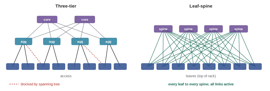
Access and aggregation were usually joined at layer 2, with the Spanning Tree Protocol blocking redundant links to prevent loops, and routing happened at the aggregation or core. The design worked well for north-south traffic, but it had three problems as east-west traffic grew.
- Unequal paths: two servers on the same access switch were one hop apart, while two servers in different aggregation blocks had to climb to the core and back down, crossing five switches. Latency and available bandwidth depended on where a server happened to sit.
- Wasted links: Spanning Tree blocks redundant links, so half of the expensive uplinks often sat idle, carrying traffic only after a failure.
- Bottlenecks at the top: all traffic between aggregation blocks squeezed through a few large core switches, which were expensive, hard to scale and large failure domains. Losing a core switch could halve the capacity of the whole data centre.
Leaf-spine
A leaf-spine fabric has just two layers. Leaf switches connect to servers, usually one or two at the top of each rack. Spine switches connect only to leaves. The rule is simple:
- Every leaf connects to every spine.
- Leaves do not connect to each other, and spines do not connect to each other.
- Servers connect only to leaves.
As a result, any server can reach any server in another rack in exactly three switch hops: up to its leaf, up to a spine, and down to the destination leaf. Every pair of racks has the same latency and the same number of paths. With \(S\) spines, there are \(S\) equal-cost paths between any two leaves, and all of them carry traffic at once.
The idea is not new. It is a form of Clos network, described by Charles Clos at Bell Labs in 1953 for telephone switching, where many small switches arranged in stages could act like one huge switch. A leaf-spine fabric is a "folded" three-stage Clos network: the first and last stages are the same leaf switches, folded back on themselves. Because it is built from many identical, relatively inexpensive switches rather than a few giant ones, it scales out simply by adding more.
Equal-cost multipath (ECMP)
For all the spines to share the load, each leaf must spread traffic across its uplinks. It does this with equal-cost multipath (ECMP) routing. The leaf sees several routes of equal cost to the destination, one through each spine, and chooses among them for each flow by computing a hash of fields in the packet header, typically the source and destination IP addresses, the protocol and the source and destination port numbers. All packets of one flow produce the same hash and take the same path, so they arrive in order; different flows spread roughly evenly across the uplinks.
ECMP works well when there are many small flows. It works less well with a few very large flows, sometimes called elephant flows. Two large flows that happen to hash to the same uplink will share it while other uplinks sit idle. AI training traffic consists of exactly this kind of large, synchronized flow, which is one reason AI fabrics use additional load-balancing techniques (Lesson 11).
Failure behaviour
Because every leaf connects to every spine, losing a spine removes one path out of \(S\) everywhere, but nothing becomes unreachable. The fabric loses \(1/S\) of its capacity. With four spines, a spine failure cuts capacity by 25%; with sixteen, by about 6%. This "graceful degradation" is a major advantage: maintenance on a spine can be done during business hours by draining traffic away from it first. Designers choose the number of spines partly to keep the impact of one failure acceptable.
Losing a leaf takes down the servers attached only to that leaf. For that reason servers that must survive a leaf failure are dual-homed to two leaves in the same rack, and applications are spread across racks so that losing one rack is tolerable.
Sizing a leaf-spine fabric
Sizing a fabric is arithmetic with a few quantities:
- The radix of a switch: its number of ports at a given speed. A switch chip's total capacity is fixed (for example 51.2 Tb/s), so it can be configured as 64 ports of 800 Gb/s, 128 of 400 Gb/s or 256 of 200 Gb/s.
- Leaf downlinks (to servers) and uplinks (to spines).
- The number of spines, which equals the number of uplinks per leaf when each leaf has one link to each spine.
- The number of leaves, which can be at most the number of ports on each spine.
The maximum number of server ports in a two-layer fabric is therefore:
Oversubscription
A leaf's oversubscription ratio compares the bandwidth it offers to servers with the bandwidth it has towards the spines:
A ratio of 1:1 is called non-blocking: if every server sends at full speed to servers in other racks, the uplinks can carry it all. A ratio of 3:1 means the uplinks can carry only a third of the worst case. Oversubscription is a cost decision. Servers rarely all transmit at full rate at once, so general-purpose cloud and enterprise fabrics commonly run at 2:1 or 3:1 at the leaf. Storage-heavy and high-performance computing fabrics aim for lower ratios, and AI training back-end fabrics are almost always built non-blocking, because every accelerator really does transmit at full rate at the same moment.
Worked problem
Oversubscription of a leaf switch
A leaf switch has 48 ports of 25 Gb/s for servers and 6 ports of 100 Gb/s for uplinks. What is its oversubscription ratio? What would it be with 8 uplinks?
Show solution
- Downlink bandwidth: \(48 \times 25 = 1200\) Gb/s.
- Uplink bandwidth with 6 uplinks: \(6 \times 100 = 600\) Gb/s.
- Ratio: \(1200 / 600 = 2\), written 2:1.
- With 8 uplinks: \(8 \times 100 = 800\) Gb/s, so \(1200/800 = 1.5\), written 1.5:1.
Answer: 2:1 with six uplinks and 1.5:1 with eight. Using all eight uplink ports also means the fabric needs eight spines.
Worked problem
How big can a fabric grow?
An architect plans a non-blocking fabric. Each leaf has 32 ports of 400 Gb/s: 16 ports go down to servers, each broken out into four 100 Gb/s server connections, and 16 go up, one to each of 16 spines. Each spine has 64 ports of 400 Gb/s. How many servers can the fabric connect at 100 Gb/s, how many leaf-to-spine links are there, and how many transceivers do those links need?
Show solution
- Check the ratio: down \(16 \times 400 = 6400\) Gb/s; up \(16 \times 400 = 6400\) Gb/s. Ratio 1:1, so non-blocking.
- Servers per leaf: \(16 \times 4 = 64\).
- Number of spines: 16 (one per uplink). Number of leaves: at most 64 (one per spine port).
- Servers: \(64 \times 64 = 4096\).
- Leaf-spine links: \(64 \text{ leaves} \times 16 \text{ uplinks} = 1024\).
- Each link needs a transceiver at each end: \(2 \times 1024 = 2048\) optics.
Answer: 4096 servers at 100 Gb/s, 1024 leaf-spine links and 2048 transceivers (plus the server-side cabling). At roughly 10 to 12 W per 400 Gb/s module, the leaf-spine optics alone draw over 20 kW.
Notice how the spine radix sets the size limit: to add a 65th leaf, a 64-port spine has no free port. The fabric must then either use bigger spines or add a third layer.
Growing beyond one fabric: five-stage Clos
When a two-layer fabric is not big enough, designers add a layer, creating a five-stage Clos network. The building is divided into pods (sometimes called fabric modules or clusters). Each pod is a leaf-spine fabric in its own right, but its spines use half their ports to connect down to the pod's leaves and half to connect up to a layer of super-spine switches. The super-spines are arranged in planes: spine number 1 in every pod connects to the switches in super-spine plane 1, spine number 2 to plane 2, and so on.
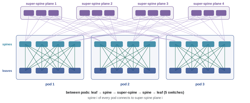
Traffic within a pod still takes three hops. Traffic between pods takes five: leaf, spine, super-spine, spine, leaf. The fabric can now grow by adding pods, up to the radix of the super-spines. Hyperscale operators publish designs of this kind that connect over 100,000 servers in a single building or campus.
Worked problem
Sizing a five-stage fabric
Each pod uses 64-port spines: 32 ports to leaves and 32 to super-spines. Each leaf has 16 uplinks (so 16 spines per pod) and serves 64 servers. Super-spines also have 64 ports. How many leaves fit in a pod, how many servers in a pod, how many pods can the fabric have, and how many servers in total?
Show solution
- Leaves per pod: each spine has 32 downward ports, so 32 leaves.
- Servers per pod: \(32 \times 64 = 2048\).
- Each super-spine has 64 ports, one per pod, so up to 64 pods.
- Total servers: \(64 \times 2048 = 131{,}072\).
- Super-spines: each of the 16 planes needs 32 super-spines to take the 32 uplinks of its spine in every pod, so \(16 \times 32 = 512\) super-spines.
Answer: 32 leaves and 2048 servers per pod, up to 64 pods and 131,072 servers, using 512 super-spine switches. Building the full fabric on day one is rarely needed: pods and super-spine planes are added as the data centre fills.
Routing the fabric: layer 3 to the rack
Early leaf-spine designs stretched layer 2 VLANs across the fabric so virtual machines could move between racks without changing IP addresses. Large layer 2 domains bring the broadcast and loop problems described in Lesson 1, so modern fabrics route at layer 3 all the way down to the leaf. Each leaf is the default gateway for its own rack's subnets, and every link between a leaf and a spine is a small routed link.
Many large operators run BGP (Border Gateway Protocol), the same protocol that ties the internet together, as the routing protocol inside the fabric, following a design published as RFC 7938. Each leaf (or each group of leaves) gets its own private autonomous system number, and the switches tell each other which subnets they can reach. BGP is well understood, scales to enormous numbers of routes and gives operators fine control over traffic. Smaller fabrics often use OSPF or IS-IS instead. This routed network of switches and links is called the underlay.
Overlays: VXLAN and EVPN
Routing to the rack is simple and robust, but some workloads still need layer 2 connectivity between racks, and cloud providers need to give each customer an isolated private network that can span the whole data centre. The answer is an overlay: a virtual network built on top of the routed underlay by wrapping (tunnelling) one packet inside another.
The most common overlay is VXLAN (Virtual Extensible LAN). A VXLAN tunnel endpoint, which can be a leaf switch or software in the server's hypervisor, takes the original Ethernet frame and wraps it in a new UDP/IP packet addressed to the tunnel endpoint at the destination. The underlay simply routes that packet like any other. VXLAN identifies each virtual network with a 24-bit VXLAN network identifier, giving over 16 million segments compared with 4094 VLANs.
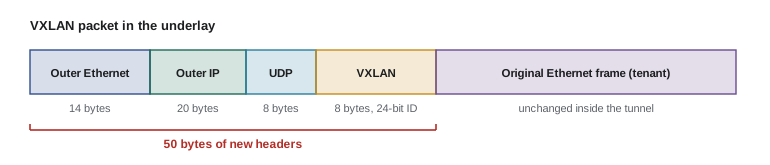
The outer headers add 50 bytes: 14 for the outer Ethernet header, 20 for IPv4, 8 for UDP and 8 for the VXLAN header. A tenant frame with a 1500-byte payload therefore becomes a 1550-byte packet in the underlay, which is why fabrics are built with a large MTU (commonly 9216 bytes on the switches) from the start.
Tunnel endpoints also need to know which MAC and IP addresses live behind which other endpoints. Rather than learning this by flooding, modern fabrics use EVPN (Ethernet VPN), an extension of BGP that distributes address information as routes. The combination, usually called EVPN-VXLAN, is the standard way to build multi-tenant layer 2 and layer 3 networks on a routed leaf-spine underlay. Lesson 4 looks at how tenants are isolated and secured on top of it.
Where the switches go
The topology has to be turned into racks, cables and pathways, and this is where network design meets facility design.
Top of rack, end of row and middle of row
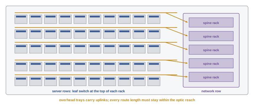
- Top of rack (ToR): one or two leaf switches sit in each server rack. Servers connect with short DAC cables inside the rack, and only the uplinks leave the rack, on fibre. This is the most common arrangement in cloud and hyperscale facilities. It minimizes cabling between racks but means many switches, each a separate device to power, cool and manage.
- End of row (EoR) or middle of row (MoR): larger leaf switches sit in dedicated network racks at the end or middle of each row, and every server is cabled to them. This uses fewer, larger switches and keeps network gear in one place, at the cost of many more cables running along the row. It is common in enterprise data centres and some AI clusters, where back-end leaves for a group of GPU racks are placed together.
Spines, super-spines and the routers that connect to carriers sit in network rows, often in a central area so that cable runs to every hall stay short. In TIA-942 terms (covered in DCE-320), these spaces are the main distribution area and horizontal distribution areas.
Distance and reach
Every link type has a maximum length. Multimode fibre optics such as 100GBASE-SR4 and 400GBASE-SR8 reach about 100 m on OM4 fibre; single-mode optics such as 400GBASE-DR4 reach 500 m, and FR4 reaches 2 km. The route length counts, not the straight-line distance: cable climbs from the rack into an overhead tray, follows the tray around corners, drops into the network row and loops through patch panels. A rule of thumb is to add 20 to 30 percent to the plan distance plus several metres at each end. If the longest leaf-to-spine run in a large hall exceeds 100 m, the design must use single-mode optics for those links, which changes the fibre plant for the whole building. This is a decision to make early, together with the network architect.
The cable plant must also be sized for the number of links. In the 4096-server example above, the 1024 leaf-spine links each need a pair of fibres for a duplex optic, or eight fibres for a parallel optic like DR4. That is thousands of fibres converging on the network row, with trays, patch panels and space for growth. Lesson 9 and DCE-320 cover how this plant is designed.
Power and cooling for network equipment
Network switches are smaller loads than servers but are not trivial. A modern 51.2 Tb/s switch with 64 ports of 800 Gb/s draws roughly 1.5 to 3 kW including its optics, and a network rack full of them can reach 15 to 30 kW, comparable with a dense server rack. Many switches move air from front to back, but some move it back to front ("reverse airflow") to suit their position in the rack; the airflow direction must match the hot-aisle and cold-aisle layout, or the switch will draw in hot exhaust air. Network rows also need A and B power feeds like any other critical equipment, since a spine failure affects every rack in the fabric.
Common mistakes
MistakeAssuming a leaf-spine fabric needs links between spines or between leaves.
InsteadLeaves connect only to spines and servers; spines connect only to leaves. Every leaf connects to every spine.
MistakeCalculating oversubscription from port counts instead of bandwidth.
InsteadCompare total downlink bandwidth with total uplink bandwidth (ports × speed on each side).
MistakeForgetting that the spine radix limits the number of leaves.
InsteadThe number of leaves can be at most the number of ports on each spine; beyond that, add a super-spine layer.
MistakeUsing straight-line distances when checking optic reach.
InsteadUse the cable route length, including rises, drops, tray routing and slack, typically 20–30% more than the plan distance.
MistakeBuilding the underlay with a 1500-byte MTU and then adding VXLAN.
InsteadVXLAN adds 50 bytes; set a large underlay MTU (often 9216) from the start.
Summary and key terms
- Modern data centre traffic is mostly east-west (server to server), which the old three-tier design handled poorly.
- In a leaf-spine fabric every leaf connects to every spine; any two racks are three hops apart with as many equal paths as there are spines.
- ECMP spreads flows across the spines by hashing header fields; very large flows can collide on one path.
- Losing one of \(S\) spines removes \(1/S\) of the fabric capacity; nothing becomes unreachable.
- Oversubscription = downlink bandwidth ÷ uplink bandwidth. General fabrics run 2:1 to 3:1; AI back-end fabrics run 1:1.
- Maximum servers = spine ports × servers per leaf. Beyond that, a five-stage Clos adds super-spines and pods.
- Fabrics route at layer 3 to the leaf (often with BGP); VXLAN overlays with EVPN provide layer 2 and multi-tenancy, adding 50 bytes per packet.
- Switch placement, optic reach, fibre counts, power and airflow direction turn the topology into a facility design problem.
- Fabric
- The set of switches and links that connects all servers in a data centre or cluster.
- East-west traffic
- Traffic between servers inside the data centre.
- North-south traffic
- Traffic between the data centre and the outside world.
- Leaf switch
- A switch that connects servers, usually at the top of a rack, and uplinks to every spine.
- Spine switch
- A switch that connects only to leaf switches.
- Clos network
- A multistage switching network built from many small switches, first described by Charles Clos in 1953.
- ECMP
- Equal-cost multipath: spreading traffic across several equal routes, usually by hashing flow headers.
- Oversubscription ratio
- The ratio of downlink to uplink bandwidth at a switch; 1:1 is non-blocking.
- Radix
- The number of ports on a switch at a given speed.
- Super-spine
- A third layer of switches connecting the spines of several pods in a five-stage Clos.
- Pod
- A self-contained leaf-spine block that connects to other pods through super-spines.
- Underlay
- The routed physical network of switches and links.
- Overlay
- A virtual network built on top of the underlay by tunnelling packets.
- VXLAN
- A tunnelling protocol that carries Ethernet frames inside UDP/IP packets, with a 24-bit network identifier.
- EVPN
- A BGP-based control plane that distributes MAC and IP address information for overlays.
- Top of rack (ToR)
- A switch placement with leaf switches inside each server rack.
Practice problems
Work each problem on paper first, then reveal the answer to check.
A leaf has 32 ports of 100 Gb/s to servers and 4 ports of 400 Gb/s to spines. Find its oversubscription ratio.
Show answer
Down 3200 Gb/s, up 1600 Gb/s: 2:1.
A fabric has 8 spines. What fraction of capacity remains if one spine fails? If two fail?
Show answer
7/8 = 87.5% with one failed; 6/8 = 75% with two.
Spines have 128 ports and each leaf serves 48 servers. What is the maximum number of servers in a two-layer fabric?
Show answer
128 leaves × 48 = 6144 servers.
In a leaf-spine fabric with 12 spines, how many equal-cost paths connect two servers on different leaves, and how many switches does each path cross?
Show answer
12 paths, each crossing 3 switches (leaf, spine, leaf).
A leaf has 48 × 25 Gb/s server ports. How many 100 Gb/s uplinks does it need to be non-blocking?
Show answer
1200 Gb/s ÷ 100 = 12 uplinks.
A fabric of 40 leaves, each with 8 uplinks to 8 spines, uses duplex single-mode optics. How many fibres do the leaf-spine links need?
Show answer
40 × 8 = 320 links × 2 fibres = 640 fibres.
Tenant virtual machines use a 1500-byte MTU over VXLAN on IPv4. What is the minimum underlay IP MTU needed? (The outer Ethernet header is not part of the IP MTU.)
Show answer
The tenant frame is 1514 bytes (1500 + 14 Ethernet header); add the 20-byte outer IP, 8-byte UDP and 8-byte VXLAN headers: 1550 bytes. Most designs simply use 9000 or more.
A spine-to-leaf route measures 70 m on the floor plan. Using a 25% allowance plus 5 m of slack at each end, can it use 100 m multimode optics?
Show answer
70 × 1.25 + 10 = 97.5 m: just within 100 m, with almost no margin. Single-mode optics would be the safer choice.
Why do AI training back-end fabrics use 1:1 oversubscription while general cloud fabrics often use 3:1?
Show answer
In AI training, every accelerator transmits at full rate at the same time during synchronization, so any oversubscription slows the whole job. General servers rarely all transmit at once, so oversubscription saves cost with little effect.
Each pod in a five-stage fabric has 16 spines with 32 uplinks each. Super-spines have 128 ports. How many pods can the fabric hold and how many super-spines are needed?
Show answer
128 pods (one per super-spine port). Each of the 16 planes needs 32 super-spines: 512 in total.
Lesson quiz · 5 questions
Score 60% or more to complete this lesson.
Create a free account to save your progress, take quizzes and earn a certificate.