
DCE-210 · Lesson 1 of 12 · 38 min
Network layers and Ethernet
A data centre without a network is a warehouse of expensive heaters. Every server depends on the network to receive work, reach storage, talk to the other servers in its cluster and send answers back to users. In a modern AI cluster, the network can cost as much as 10 to 20 percent of the computing equipment, and a poorly designed one can leave thousands of accelerators idle while they wait for data.
Data centre engineers do not have to configure routers, but they do have to design the spaces, power, cooling, cable pathways and fibre plant that the network needs, and they work alongside network architects every day. To do that well, an engineer needs to speak the language: what the layers are, what Ethernet actually sends down the wire, how fast the links run and why those speeds come in the steps they do. This chapter builds that foundation. The rest of the course climbs from the single link to the fabric inside a building, the connections between buildings and carriers, the optical systems that carry the traffic, and the special networks built for AI training.
Why networks are built in layers
Sending data between two computers involves many separate problems: turning bits into light or voltage, deciding which device on a cable may talk, finding a path across many networks, recovering lost packets, and presenting the data to an application. Engineers handle this by dividing the work into layers. Each layer does one job, relies on the layer below and offers a service to the layer above. A web browser does not need to know whether its data crosses copper, fibre or radio; a fibre transceiver does not need to know whether it is carrying a video or a bank transfer.
Two layer models are in common use. The OSI (Open Systems Interconnection) reference model has seven layers and is mostly used as a vocabulary. The TCP/IP model, which describes how the internet actually works, has four or five. Engineers mix the two: they say "layer 2" and "layer 3" from the OSI model while using TCP/IP protocols.
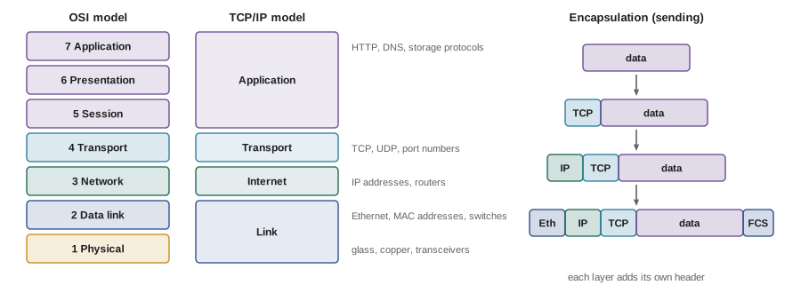
The layers that matter most in a data centre
- Layer 1, physical: the cables, connectors, transceivers and the electrical or optical signals. This is where data centre engineers spend most of their time: fibre types, loss budgets, cable trays, patch panels and the power and heat of optics.
- Layer 2, data link: Ethernet. It moves frames between devices on the same network segment, using 48-bit MAC (media access control) addresses burned into each network interface. Switches work at this layer.
- Layer 3, network: IP (Internet Protocol). It moves packets between different networks using IP addresses, and routers choose the path. Most modern data centre fabrics route at layer 3 right down to the top-of-rack switch.
- Layer 4, transport: TCP (Transmission Control Protocol) provides a reliable, ordered byte stream and resends lost data; UDP (User Datagram Protocol) sends individual datagrams with no guarantees and is used where speed matters more than reliability, or where a higher layer handles recovery itself. Port numbers at this layer identify the application (443 for secure web traffic, for example). Lesson 2 looks at how TCP paces traffic and what limits its speed.
- Layers 5 to 7: application protocols such as HTTP for web traffic, DNS for name lookups, and storage protocols such as NVMe over Fabrics and iSCSI.
Encapsulation
As data passes down the layers, each layer adds its own header, a little like putting a letter in an envelope, then putting that envelope in a courier bag, then putting the bag in a shipping container. An application's data gets a TCP header (20 bytes without options), then an IP header (20 bytes for IPv4, 40 bytes for IPv6), then an Ethernet header (14 bytes) and a 4-byte trailer called the frame check sequence (FCS). At the other end each layer strips off its header and passes the contents up.
Every header is overhead: it uses link capacity but carries no user data. Engineers care about overhead because it decides how much of a link's headline speed is actually usable, which you will calculate shortly.
Ethernet
Ethernet was invented at Xerox PARC in 1973 to connect computers over a shared coaxial cable at about 3 Mb/s. Fifty years later the same name covers links running at 800 Gb/s over fibre, and the frame format is almost unchanged. Ethernet is standardized by the IEEE 802.3 working group, and each speed and medium has its own designation, such as 100GBASE-SR4: 100 Gb/s, baseband signalling, short reach, four lanes.
Early Ethernet devices shared one cable and had to take turns, detecting collisions when two talked at once. Modern data centre Ethernet is entirely switched and full duplex: each device has its own dedicated link to a switch port, both directions carry traffic at the full rate simultaneously, and collisions do not happen. A "100 Gb/s link" therefore carries 100 Gb/s in each direction at once.
The Ethernet frame
An Ethernet frame carries a payload of 46 to 1500 bytes in its standard form. The payload is usually an IP packet. Around it sit:
- Preamble and start frame delimiter (8 bytes): a fixed pattern that lets the receiver lock on to the signal. Not counted as part of the frame, but it uses time on the wire.
- Destination and source MAC addresses (6 bytes each).
- EtherType (2 bytes): says what the payload is, for example 0x0800 for IPv4 or 0x86DD for IPv6.
- Payload (46 to 1500 bytes). Short payloads are padded up to 46 bytes so the frame is at least 64 bytes long.
- Frame check sequence (4 bytes): a CRC-32 checksum. A receiver that finds a mismatch drops the frame.
- Interframe gap (12 bytes of idle time): a mandatory quiet period between frames.
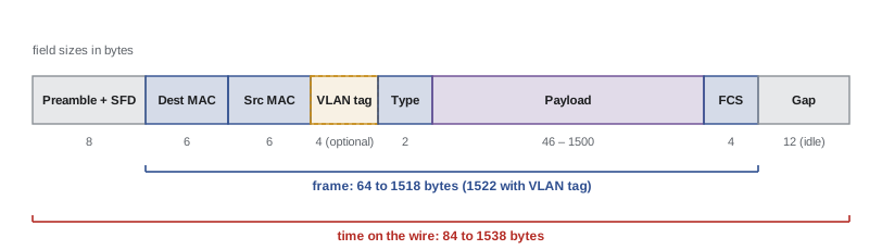
The largest payload a link carries is its MTU (maximum transmission unit). The standard Ethernet MTU is 1500 bytes. Many data centres enable jumbo frames, usually with a 9000-byte MTU, so that storage and high-performance traffic spends less of the link on headers and the hosts handle fewer packets per second. Jumbo frames must be enabled consistently on every device in a path; a single device with a 1500-byte MTU in the middle will drop or fragment the large frames, and this is a classic cause of mysterious failures.
The bytes on the wire for one full-size frame are:
so even before IP and TCP are counted, Ethernet itself uses 38 of every 1538 bytes.
Worked problem
How much of a 10 Gb/s link is usable?
A server sends a long file over TCP/IPv4 using standard 1500-byte frames on a 10 Gb/s Ethernet link. What fraction of the link carries the file, and what is the usable data rate? Repeat for 9000-byte jumbo frames.
Show solution
- Each frame occupies 1538 bytes of wire time (from above).
- Inside the 1500-byte payload, the IPv4 header uses 20 bytes and the TCP header 20 bytes, leaving 1460 bytes of file data.
- Efficiency with standard frames: \(1460 / 1538 = 0.949\), or 94.9%.
- Usable rate: \(0.949 \times 10 = 9.49\) Gb/s.
- With jumbo frames the wire time is \(8 + 14 + 9000 + 4 + 12 = 9038\) bytes and the data is \(9000 - 40 = 8960\) bytes.
- Efficiency: \(8960 / 9038 = 0.991\), or 99.1%, giving 9.91 Gb/s.
Answer: About 9.49 Gb/s (94.9%) with standard frames and 9.91 Gb/s (99.1%) with jumbo frames. Real throughput is a little lower again because of TCP acknowledgements, retransmissions and host limits.
Small frames and packets per second
Overhead is worst for small frames. A minimum 64-byte frame still needs its 8-byte preamble and 12-byte gap, so it occupies 84 bytes, or 672 bits, of wire time. The maximum number of frames a link can carry per second is therefore:
For 10 Gb/s this is 14.88 million frames per second; for 100 Gb/s, 148.8 million. Switches and network cards are specified by whether they can forward at "line rate" for minimum-size frames, because handling each frame takes a fixed amount of work regardless of its size. Workloads with many small messages, such as some databases and AI inference serving, stress packets per second rather than bandwidth.
Serialization delay
Putting a frame onto a link takes time: the number of bits divided by the link rate. This is the serialization delay. A full-size frame of 1538 bytes (12,304 bits) takes 12.3 µs at 1 Gb/s, 1.23 µs at 10 Gb/s and 0.123 µs at 100 Gb/s. A switch that stores a whole frame before forwarding it adds at least one serialization delay at each hop, which is one reason faster links also reduce latency.
Switching and MAC addresses
A MAC address is 48 bits, written as six pairs of hexadecimal digits such as 3c:fd:fe:a4:01:7b. The first 24 bits identify the manufacturer (the organizationally unique identifier); the rest are assigned by the manufacturer. A layer 2 switch learns which MAC addresses live on which port by reading the source address of every frame it receives, and stores them in a MAC address table. When a frame arrives for a destination it knows, it sends the frame out of that one port only. When the destination is unknown, or the frame is a broadcast, it floods the frame out of every port in the same network segment.
Flooding is fine in a small network but becomes a problem as layer 2 domains grow: every broadcast reaches every host, MAC tables fill up, and a loop in the cabling can make frames circulate forever until the network collapses in a broadcast storm. The Spanning Tree Protocol prevents loops by blocking redundant links, but blocked links waste capacity. This is one of the main reasons modern data centres keep layer 2 domains small and route at layer 3, as the next chapter explains.
VLANs
A VLAN (virtual LAN) divides one physical switch network into separate logical networks. The IEEE 802.1Q standard inserts a 4-byte tag after the source MAC address containing a 12-bit VLAN identifier. Twelve bits give 4096 values, of which 0 and 4095 are reserved, so a network can have at most 4094 VLANs. That was plenty for an office building but far too few for a cloud provider with millions of customers, which is why data centres use overlay technologies such as VXLAN with a 24-bit identifier (over 16 million segments), covered in the next chapter.
IP addressing in brief
An IPv4 address is 32 bits, written as four decimal numbers such as 10.20.4.17. Addresses are grouped into subnets described by a prefix length: 10.20.4.0/24 means the first 24 bits identify the network and the last 8 bits identify hosts, giving 256 addresses. The first (network) and last (broadcast) addresses are reserved, leaving 254 usable host addresses. In general a subnet with prefix length \(p\) has \(2^{32-p}\) addresses.
The roughly 4.3 billion IPv4 addresses ran out years ago. Data centres use private address ranges such as 10.0.0.0/8 internally and translate to public addresses at the edge. IPv6 uses 128-bit addresses, written in hexadecimal such as 2001:db8:4a::17, and a standard subnet is a /64, which holds \(2^{64}\) addresses, more than enough for any rack. Large operators increasingly run IPv6 internally for exactly that reason.
Within a subnet, a host finds the MAC address that matches an IP address using ARP (Address Resolution Protocol) in IPv4 or Neighbour Discovery in IPv6. To reach anything outside its subnet, a host sends the frame to its default gateway, which in a modern data centre is usually the top-of-rack switch.
Worked problem
Sizing a rack subnet
A rack holds 40 servers. Each has one address for its main interface and one for its management controller, on separate subnets. The switch needs one address in each subnet as the gateway. What is the smallest IPv4 subnet for each, and how many addresses are left over?
Show solution
- Each subnet needs 40 hosts + 1 gateway = 41 usable addresses.
- A /27 has \(2^{5} = 32\) addresses (30 usable): too small.
- A /26 has \(2^{6} = 64\) addresses (62 usable): enough.
- Spare addresses: \(62 - 41 = 21\) per subnet.
Answer: A /26 for each subnet, with 21 spare addresses in each. Many operators simply give every rack a /24 for simplicity, since private address space is plentiful.
Ethernet speeds and lanes
Ethernet speed has grown by about a factor of ten every decade or so, and data centres have adopted each step as soon as it became affordable. The common data centre speeds today are 25 and 100 Gb/s to servers, 100 and 400 Gb/s between switches, and 400 and 800 Gb/s in AI clusters.
| Speed | Typical lane structure | Typical use |
|---|---|---|
| 1 GbE | 1 × 1.25 Gbaud | Management networks, building systems |
| 10 GbE | 1 × 10 Gb/s | Older servers, management |
| 25 GbE | 1 × 25 Gb/s | Server connections |
| 100 GbE | 4 × 25 Gb/s, or 2 × 50 Gb/s, or 1 × 100 Gb/s | Servers and switch uplinks |
| 400 GbE | 8 × 50 Gb/s or 4 × 100 Gb/s | Spine links, AI servers |
| 800 GbE | 8 × 100 Gb/s | AI cluster fabrics, spine links |
High speeds are built from lanes. A lane is one electrical or optical channel, and a switch chip connects to its ports through SerDes (serializer/deserializer) circuits, each running one lane. A 100 Gb/s port might be four 25 Gb/s lanes; an 800 Gb/s port is eight 100 Gb/s lanes. The industry moves forward by doubling the lane rate (10, 25, 50, 100 and now 200 Gb/s per lane), and each doubling allows a new top port speed with the same number of lanes. Ethernet at 1.6 Tb/s built on 200 Gb/s lanes is being standardized, and first products are already appearing.
Because lanes can be split, one physical port can often be broken out into several slower ports. A 400 Gb/s port with four 100 Gb/s lanes can serve four separate 100 Gb/s servers using a breakout cable. Breakouts appear constantly in cabling designs and affect how many fibres and connectors each rack needs.
NRZ and PAM4
Up to 25 Gb/s per lane, Ethernet used NRZ (non-return-to-zero) signalling: two signal levels, one bit per symbol. To go faster without doubling the symbol rate, 50 and 100 Gb/s lanes use PAM4 (four-level pulse amplitude modulation): four levels carry two bits per symbol. A 100 Gb/s PAM4 lane runs at about 53 gigabaud rather than 106.
PAM4 has a cost. With four levels squeezed into the same signal swing, the gap between levels is one third as large, so the signal is much more sensitive to noise. PAM4 links therefore rely on forward error correction (FEC): extra bits that let the receiver correct errors without retransmission. FEC adds a little latency (on the order of 100 nanoseconds) and some power. This is why the error-rate and loss specifications for modern optics and cables are so strict, and why a dirty connector that a 10 Gb/s link would tolerate can take down a 400 Gb/s link.

Bits and bytes
Network speeds are always quoted in bits per second; file and storage sizes are quoted in bytes. One byte is 8 bits. Mixing them up is the single most common error in network calculations, and it is an error by a factor of eight. Network rates also use decimal prefixes (1 Gb/s is \(10^9\) bits per second), while operating systems sometimes report memory and file sizes in binary units (1 GiB is \(2^{30}\) bytes, about 7% more than \(10^9\)). For quick engineering estimates, decimal units are fine; just say which you are using.
Worked problem
How long does a transfer take?
An engineer needs to copy a 1 TB (\(10^{12}\) bytes) data set between two servers over TCP with standard 1500-byte frames. Estimate the time on a 10 Gb/s link and on a 100 Gb/s link.
Show solution
- Convert to bits: \(10^{12} \times 8 = 8 \times 10^{12}\) bits.
- Usable rate on 10 Gb/s with 94.9% efficiency: 9.49 Gb/s.
- Time: \(8 \times 10^{12} / 9.49 \times 10^{9} = 843\) s, about 14 minutes.
- On 100 Gb/s the usable rate is 94.9 Gb/s and the time is 84 s.
Answer: About 14 minutes at 10 Gb/s and under 1.5 minutes at 100 Gb/s, assuming the disks and servers can keep up. In practice storage speed often becomes the bottleneck at 100 Gb/s.
Copper or fibre?
At these speeds, signals on copper fade quickly. Inside a rack, the cheapest connection is a direct attach copper (DAC) cable: a fixed twinax cable with connectors on both ends and no optics, good for about 2 to 3 m at 100 Gb/s per lane, and drawing almost no power. Active electrical cables (AEC) add signal-conditioning chips to reach about 5 to 7 m. Anything longer uses fibre and optical transceivers, which convert electrical lanes to light and back. Transceivers plug into switch and network-card ports in standard form factors: SFP28 for 25 Gb/s, QSFP28 for 100 Gb/s, and QSFP-DD or OSFP for 400 and 800 Gb/s. Twisted-pair copper (category 6A cabling with RJ45 connectors) remains common for management networks, building systems and wireless access points at 1 to 10 Gb/s.
Optics matter to the facility engineer for three reasons. They are a large share of network cost. They consume power: an 800 Gb/s transceiver draws roughly 13 to 18 W, and a large AI cluster can have tens of thousands of them. And they decide which fibre type the building must provide and how much loss the cabling may have. Lesson 9 covers fibre and optics in depth.
The networks in a data centre
A data centre usually runs several separate networks, and each needs its own cabling, space and power:
- The production or front-end network carries traffic between servers and to the outside world.
- The storage network connects servers to storage systems; in many facilities it now shares the production Ethernet fabric (Lesson 5).
- The back-end or scale-out network, in AI and high-performance computing clusters, connects accelerators to each other for training. It is often the largest and most expensive network in the building (Lesson 11).
- The out-of-band management network connects each server's baseboard management controller (BMC), switch management ports and power distribution units, so that equipment can be controlled even when the production network is down. It runs at 1 Gb/s on copper and must be completely independent of the production network.
- Building and facility networks connect the building management system, electrical power monitoring, security cameras and access control. These operational technology networks are kept separate from IT networks for security.
Each of these networks shows up in the facility design as cable trays, patch panels, rack positions, switch power and cooling. Forgetting one, usually management or facility networks, is a common source of late changes during construction.
How this course is organized
The course moves from inside the rack to the wider world:
- Lesson 2 explains latency, TCP and quality of service: why networks feel fast or slow.
- Lessons 3 to 6 cover the data centre network: leaf-spine fabrics, virtual networks and security, storage networks, and the switches, routers and transceivers they are built from.
- Lessons 7 and 8 leave the building: carriers, peering and interconnection, then internet routing, content delivery and enterprise WANs.
- Lesson 9 covers optical transport, and Lesson 10 telecommunications facilities, −48 V DC power and timing.
- Lesson 11 examines the networks of AI clusters, and Lesson 12 network operations, reliability and the technologies ahead.
Common mistakes
MistakeMixing up bits and bytes, for example dividing a file size in bytes by a link speed in bits per second.
InsteadConvert bytes to bits (× 8) before dividing by a rate in bits per second.
MistakeAssuming a 10 Gb/s link carries 10 Gb/s of user data.
InsteadHeaders, preamble and gaps take about 5% with standard frames; usable TCP throughput is about 9.5 Gb/s.
MistakeThinking a 100 Gb/s link is 100 Gb/s total, shared between directions.
InsteadData centre Ethernet is full duplex: 100 Gb/s in each direction at the same time.
MistakeEnabling jumbo frames on servers but not on every switch in the path.
InsteadThe MTU must be consistent end to end, or large frames will be dropped.
MistakeForgetting the management and facility networks in the cabling and rack design.
InsteadList every network at the start of design; each needs ports, pathways, power and space.
Summary and key terms
- Networks are built in layers. Data centre engineers work mostly at layer 1 (physical), and need to understand layer 2 (Ethernet switching) and layer 3 (IP routing).
- Each layer adds a header (encapsulation). A full-size Ethernet frame occupies 1538 bytes of wire time for 1500 bytes of payload.
- TCP over IPv4 with 1500-byte frames uses about 94.9% of the link; 9000-byte jumbo frames raise this to about 99.1%.
- A minimum 64-byte frame uses 672 bits of wire time, so a link carries at most (rate ÷ 672) frames per second: 14.88 million at 10 Gb/s.
- Switches learn MAC addresses and forward frames within a layer 2 domain; VLANs (12-bit, 4094 usable) separate networks logically.
- A subnet with prefix length \(p\) has \(2^{32-p}\) IPv4 addresses, two of which are reserved.
- High-speed Ethernet is built from lanes (25, 50, 100, 200 Gb/s); PAM4 carries 2 bits per symbol and needs forward error correction.
- Copper DAC cables serve a few metres; everything longer uses fibre and optical transceivers, which add cost, power and heat.
- OSI model
- A seven-layer reference model of network functions, from physical (1) to application (7).
- Encapsulation
- Wrapping data from a higher layer inside the header and trailer of a lower layer.
- Ethernet
- The IEEE 802.3 family of layer 2 standards used for almost all data centre networking.
- Frame
- The unit of data at layer 2, with MAC addresses, a payload and a checksum.
- MAC address
- A 48-bit layer 2 address assigned to a network interface.
- MTU
- Maximum transmission unit: the largest payload a link carries, 1500 bytes standard or about 9000 with jumbo frames.
- VLAN
- Virtual LAN: a logical layer 2 network identified by a 12-bit tag.
- Subnet
- A block of IP addresses sharing a common prefix, written as address/prefix length.
- Full duplex
- Transmission in both directions at the same time, each at the full link rate.
- Serialization delay
- The time to put all the bits of a frame onto a link: frame bits ÷ link rate.
- Lane
- One electrical or optical channel; ports are built from one or more lanes.
- PAM4
- Four-level pulse amplitude modulation, carrying 2 bits per symbol.
- Forward error correction (FEC)
- Redundant bits that let a receiver correct transmission errors without retransmission.
- DAC
- Direct attach copper: a short twinax cable with fixed connectors, used within a rack.
- Transceiver
- A pluggable module that converts electrical signals to optical (or electrical) signals for a link.
- Out-of-band management
- A separate network for controlling equipment independently of the production network.
Practice problems
Work each problem on paper first, then reveal the answer to check.
What fraction of a link carries payload when Ethernet frames carry a 1000-byte payload? (Count preamble, header, FCS and gap.)
Show answer
Wire time = 8 + 14 + 1000 + 4 + 12 = 1038 bytes; 1000/1038 = 96.3%.
How many minimum-size frames per second can a 25 Gb/s link carry?
Show answer
25 × 10⁹ ÷ 672 = 37.2 million frames per second.
Find the serialization delay of a 9038-byte jumbo frame (wire time) on a 25 Gb/s link.
Show answer
9038 × 8 = 72,304 bits; ÷ 25 × 10⁹ = 2.89 µs.
How many usable host addresses are in a /28 IPv4 subnet?
Show answer
2⁴ = 16 addresses, minus 2 reserved = 14.
A server backs up 500 GB over a 25 Gb/s link at 94.9% efficiency. How long does it take?
Show answer
500 × 10⁹ × 8 = 4 × 10¹² bits; ÷ (0.949 × 25 × 10⁹) = 169 s, under 3 minutes.
Why can a network have at most 4094 VLANs?
Show answer
The 802.1Q tag has a 12-bit identifier (4096 values), and values 0 and 4095 are reserved.
A 400 Gb/s port uses 4 lanes. What is the lane rate, and how many 100 Gb/s servers could it serve with a breakout cable?
Show answer
100 Gb/s per lane; four servers.
A 100 Gb/s PAM4 lane runs at about 53 gigabaud. Why not 106?
Show answer
PAM4 carries two bits per symbol, so it needs about half the symbol rate of two-level signalling.
A rack has 32 servers, each with two 100 Gb/s ports cabled to the top-of-rack switch with DAC. How much server-facing bandwidth does the switch need, in each direction?
Show answer
32 × 2 × 100 = 6400 Gb/s, or 6.4 Tb/s, in each direction.
Name the five networks commonly found in a data centre and say which must keep working when the production network fails.
Show answer
Production (front-end), storage, back-end (AI/HPC), out-of-band management and building/facility networks. The out-of-band management network must be independent so equipment can be controlled when production is down.
Lesson quiz · 5 questions
Score 60% or more to complete this lesson.
Create a free account to save your progress, take quizzes and earn a certificate.