
BAS-230 · Lesson 9 of 12 · 23 min
Hydronic pumping and differential pressure control
▶ Video coming soon A video version of this lesson is on the way.
Sophie's last Wednesday session, on November 11, came at the end of a long day for Callie, who had spent it on Ninefield's roof checking out the new RTU-1 controller. Two days earlier Callie had found why Ninefield's chilled water differential pressure transmitter jumped: its cable shield was grounded at both ends and ran beside the VFD output cables. BAS-130 had shown how that noise made the secondary pump loop hunt in October. "So the loop's quiet now," Sophie said, "and the pumps still run at 52 hertz all day. That isn't a noise problem. That's the sequence." She put the 1998 pumping paragraphs and Quillon's draft for the spring retro-commissioning side by side.
Why variable-speed pumping needs a pressure setpoint
In a hydronic system with two-way control valves, the flow the system needs changes all the time as the valves open and close. A variable-speed pump is controlled to hold a differential pressure, measured between a supply and a return pipe, so that every valve has enough pressure across it to deliver its design flow when it opens fully. When the valves close, the pressure rises, the pump slows down, and the flow and pump energy fall. The differential pressure setpoint is therefore the single most important number in a variable-flow pumping sequence: too low, and the far coils starve; too high, and the pumps waste energy and push water through valves that cannot hold it back.
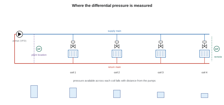
Where the sensor goes
The location of the differential pressure sensor decides how much the pressure can fall at part load. A sensor across the headers at the pumps must be set high enough to cover the pressure drop along the mains to the farthest coil at full flow, plus the pressure that coil and its valve need. At part load the main losses fall with the square of the flow, but the setpoint at the pumps stays the same, so the pumps keep making pressure the system no longer needs. A sensor out at the farthest coil only has to be set to what that coil and its valve need, and the pumps automatically make less pressure as the main losses fall.
| Sensor location | Setpoint must cover | Part-load behaviour |
|---|---|---|
| Across headers at the pumps | Main losses at full flow plus the farthest coil and valve | Pumps hold the full-flow pressure even at low flow |
| Across the farthest coil and valve | That coil and valve only | Pressure at the pumps falls as main losses fall |
| Several remote sensors, lowest selected | Each coil and valve at its location | Works when the farthest coil changes with load |
Ninefield's 1998 sensor measured across the supply and return headers in the penthouse, a few metres from the pumps, with a fixed setpoint of 100 kPa. That number had been chosen by the original balancer at full flow with all four air handlers' valves wide open. At a typical part load the coils needed nothing like that pressure, and the pumps ran at 52 Hz all day to provide it.
Resetting the differential pressure
Moving the sensor helps, but the best results come from resetting the setpoint from the valves themselves. If no valve is nearly fully open, every coil has more pressure than it needs and the setpoint can fall; when one or two valves are almost fully open, they are close to running short, and the setpoint should rise. This is trim and respond again, exactly as lesson 4 applied it to duct static pressure, with valve position requests instead of box damper requests. Guideline 36's plant sequences reset pump differential pressure this way.
| Setting | Sample value in Quillon's draft |
|---|---|
| Minimum and maximum setpoint | 35 to 100 kPa |
| Time step | 3 minutes |
| Request | A coil valve above 95 open for 2 minutes |
| Ignored requests | 1 |
| Trim | −2 kPa |
| Respond | +3 kPa per request, maximum +7 kPa |
Sophie's draft did both: it added a second differential pressure sensor across the farthest air handler's coil and valve, at the far end of the penthouse mechanical room, and reset the setpoint by trim and respond from the four air handlers' valve positions, with the header sensor kept as a high limit to protect the pipework. With only four large coils, she set the ignored requests to one, so that a single air handler with a stuck-open valve could not hold the whole system at maximum.
What the savings look like
Pump power falls steeply with speed. The affinity laws say that, for a given pump and system, flow is proportional to speed, pressure to the square of speed and power to the cube of speed. Real systems with a differential pressure setpoint do not follow the cube law exactly, because the setpoint holds some pressure even at zero flow, but the laws show why even a modest speed reduction saves a lot of energy.
Worked problem
Estimating pump power at a lower speed
Ninefield's duty secondary pump draws about 15 kW at 52 Hz. If differential pressure reset lets it run at 40 Hz for most of the day, roughly what power does the affinity law predict?
Show solution
- Speed ratio: 40 ÷ 52 = 0.769.
- Power ratio: 0.769³ = 0.455.
- Power: 15 × 0.455 = 6.8 kW.
Answer: About 6.8 kW instead of 15 kW, a reduction of more than half, before allowing for the drive and motor efficiency at the lower speed. The estimate is the best case; the real figure will be somewhat less because of the fixed part of the setpoint.
Lower pump pressure also helps the low delta-T problem from lesson 7. With less pressure across them, the coil valves control more steadily near their closed positions, and water that would have been pushed through partly open valves no longer short-circuits the coils. Sophie said the differential pressure reset, the valve conversions and the supply air reset were really one fix in three parts, and the draft sequence presented them that way.
Pump staging and lead-standby
Ninefield's secondary pumps are one duty and one standby, each able to carry the full flow. The sequence runs the duty pump on the differential pressure loop and starts the standby only if the duty pump fails to prove, as BAS-130's failover test at Ninefield confirmed. Plants with two or more pumps that run together stage them by speed or by flow: the second pump starts when the first runs above a high speed for some minutes, and stops when both run below a lower speed. Running two pumps at moderate speed can use less energy than one pump at full speed, depending on the pump curves, and good sequences use the manufacturer's curves to choose the staging points.
| Pumping rule | Typical setting |
|---|---|
| Minimum speed | About 20 to 30 Hz, set by motor cooling and the pump manufacturer |
| Start second pump (parallel duty) | First pump above about 90 in 100 speed for 10 minutes |
| Stop second pump | Both pumps below about 50 in 100 speed for 15 minutes |
| Failover | Standby starts at once if the duty pump fails to prove |
| Rotation | Lead role changes weekly or by run hours |
Every variable-speed pump sequence needs a minimum speed. Below it, some motors overheat because their cooling fan turns too slowly, and the pump may not deliver enough flow for chillers or boilers that need a minimum. The chiller's minimum evaporator flow from lesson 7 and the boiler's minimum flow from lesson 6 are protected by the primary pumps or bypasses, not by the secondary pump's speed, but the sequence must say which device protects each one.
Tuning and stability
Differential pressure loops are fast. The pressure responds within a second or two of a speed change, and a loop tuned for a slow process will overshoot and hunt. BAS-130 traced Ninefield's hunting in October to a 15 second input filter on the transmitter, a very long lag for such a fast process, and the real cause turned out to be electrical noise, which BAS-120 fixed. A good sequence specifies the control loop's update rate and the transmitter's filter, and the commissioning test from BAS-410 should include a step change in setpoint to check that the loop settles without hunting.
When the setpoint is reset by trim and respond, the reset must be much slower than the loop. Sophie's draft used a 3 minute time step against a loop that settled in well under a minute, so that the loop always had time to reach each new setpoint before the reset moved it again. A reset faster than its loop makes the two fight, which looks on a trend like hunting with no obvious cause.
Worked problem
Why a remote sensor lets the pumps slow down
At full flow, Ninefield's farthest coil and valve need 35 kPa and the mains between the pumps and that coil lose 65 kPa, so the header setpoint of 100 kPa just covers the system. At half flow, the main losses fall with the square of the flow. How much pressure do the pumps actually need at the headers at half flow?
Show solution
- Main losses at half flow: 65 × 0.5² = 65 × 0.25 = 16.25 kPa.
- Pressure needed at the headers: 35 + 16.25 = 51.25 kPa, about 51 kPa.
Answer: At half flow the system needs about 51 kPa at the headers, but the 1998 sequence held 100 kPa. With the sensor at the farthest coil set to 35 kPa, the pumps make only what the system needs.
Minimum flow and bypasses
Variable-flow systems still need some flow. Pumps have a minimum flow below which they overheat and wear, and in primary-only plants the chillers have a minimum evaporator flow below which they trip. When almost every coil valve is closed, something must keep water moving. The usual answers are a bypass valve between supply and return near the pumps, opened by the sequence when the measured flow falls toward the minimum, or a small number of three-way valves left at the ends of the system to provide a permanent path.
A modulating bypass is better than a fixed one, because a fixed bypass carries water all year, raising pump energy and lowering the return temperature even when the system flow is high. The sequence opens the bypass only when the flow meter reads below the minimum and closes it as soon as the coils need the flow again. In a primary-secondary plant like Ninefield's, the primary pumps and the decoupler already protect the chillers, so the secondary bypass only has to protect the secondary pumps.
When the differential pressure signal fails
If the differential pressure transmitter fails, a reset sequence has nothing to control to. The pumps must not run to maximum speed and stay there, nor drop to minimum and starve the coils. A typical response is to hold the pumps at a fixed speed known to serve the design load, often found during balancing, and raise an alarm. Where there are two remote sensors, the sequence can drop the failed one and control to the other. Sophie's draft held the Ninefield pumps at 45 Hz on a failed sensor, a value she flagged for Prakash to confirm on site in the spring.
| Condition | Sequence response |
|---|---|
| Remote sensor fails, header sensor good | Control to the header sensor at its fixed setpoint, alarm |
| All differential pressure sensors fail | Hold pumps at a fixed safe speed, alarm |
| Duty pump fails to prove | Start the standby pump, alarm |
| Flow below pump minimum | Open the bypass valve to hold the minimum |
These fallbacks are dull to write and easy to forget, which is exactly why reviewers check for them. Ninefield's 1998 text, Sophie noted, did not say what the pumps should do if the transmitter failed, and the noisy shield Callie fixed had in effect been a failing sensor for years.
Common mistakes
MistakeSetting the differential pressure from full-flow balancing and never changing it.
InsteadReset it from valve positions, within limits, at a rate much slower than the loop.
MistakePutting the only sensor across the headers at the pumps.
InsteadMeasure across the farthest coil and valve, or select the lowest of several remote sensors.
MistakeLetting one stuck-open valve hold the system at maximum.
InsteadIgnore at least one request, and let operators exclude a known faulty coil.
MistakeForgetting a minimum pump speed.
InsteadSet a minimum from the motor and pump manufacturer, and say which device protects chiller and boiler minimum flows.
MistakeFiltering a fast pressure signal heavily to hide noise.
InsteadFix the noise at the wiring, as BAS-120 did, and keep the filter short.
Summary and key terms
- Variable-speed pumps hold a differential pressure so that every open valve can deliver its design flow.
- A sensor at the pumps must cover main losses at full flow; a remote sensor lets the pumps slow as those losses fall.
- Trim and respond from valve positions resets the setpoint to what the coils need.
- Pump power falls roughly with the cube of speed, so modest speed reductions save a lot of energy.
- Lower pump pressure helps coil valves control and reduces low delta-T.
- Duty and standby pumps fail over on proof; parallel pumps stage by speed or flow with delays.
- Pressure loops are fast, and any reset of their setpoint must be much slower.
- Differential pressure
- The pressure difference between supply and return pipes at a measured point.
- Remote sensor
- A differential pressure sensor across the farthest or hardest-to-serve coil and its valve.
- Affinity laws
- Rules relating pump flow, pressure and power to speed.
- Valve request
- A signal sent when a coil valve is nearly fully open for some time.
- Duty and standby
- A pumping arrangement in which one pump runs and the other starts on failure.
- Parallel pumping
- Two or more pumps running together into a common header.
- Minimum speed
- The lowest speed a variable-speed pump is allowed to run.
- Main losses
- The pressure lost in the supply and return mains between the pumps and a coil.
Practice problems
Work each problem on paper first, then reveal the answer to check.
A pump draws 10 kW at 60 Hz. Roughly what at 45 Hz?
Show answer
(45 ÷ 60)³ = 0.42; about 4.2 kW.
Main losses 60 kPa at full flow. What at 70 in 100 flow?
Show answer
60 × 0.7² = 29.4 kPa.
Trim −2 kPa, respond +3 kPa per request, 1 ignored, maximum +7. Three requests. Net change?
Show answer
(3 − 1) × 3 = 6; net −2 + 6 = +4 kPa.
Why is the reset time step much longer than the pressure loop's settling time?
Show answer
So the loop reaches each setpoint before the reset moves it again.
Name one reason for a minimum pump speed.
Show answer
Motor cooling, or the minimum flow a chiller or boiler needs.
Lesson quiz · 5 questions
Score 60% or more to complete this lesson.
Create a free account to save your progress, take quizzes and earn a certificate.