
BAS-230 · Lesson 2 of 12 · 23 min
Air handler start, stop and safeties
▶ Video coming soon A video version of this lesson is on the way.
Sophie's sequence evening on Wednesday, September 23 was about the most important paragraphs in any air handler sequence: the ones that start the unit, stop it and protect it. "Most sequences put these near the front, and most programmers skim them, because they look simple," she said. "Then the unit starts against closed dampers, or trips its freezestat every cold morning, or comes back after a power failure with every fan in the building at once." The document on the table was again Tilden Hall's AHU-1, and next to it Sophie laid a copy of Ninefield Tower's penthouse air handler sequence, written in 1998 and much more detailed.
The start sequence
Starting an air handler is a sequence of steps, each waiting for the one before it. The outdoor and return dampers must move to their start positions before the fan pushes against them; the fan must be proven running before its loops are allowed to act; and the loops should begin from safe outputs, not from wherever their integral terms happened to be. BAS-130 traced how AHU-1 does this, and BAS-220 showed the timers and permissives that carry it out. Here the question is how a sequence describes it, and what a good description must include.
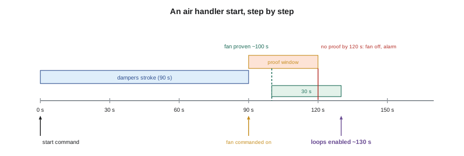
AHU-1's 2009 sequence describes its start in four sentences, and Sophie turned each into a line of the timeline. When the schedule or a mode calls for the unit, the outdoor air and return dampers are commanded to their start positions. When the outdoor damper's end switch confirms it is open, or after a 90 second delay if no end switch is fitted, the supply fan starts. If fan status is not proven within 30 seconds, the fan is commanded off and a fan failure alarm is raised. Thirty seconds after proof, the supply air temperature and duct static pressure loops are enabled and the VFD ramps from its minimum speed.
Worked problem
Timing an air handler start
Using AHU-1's sequence, the outdoor damper actuator takes 90 seconds to stroke, the fan proves 10 seconds after its command, and the loops are enabled 30 seconds after proof. How long after the start command do the loops take over? What is the latest the loops could take over without a failure alarm?
Show solution
- Normal case: 90 s for the damper, 10 s to prove, 30 s delay: 90 + 10 + 30 = 130 s.
- Latest case without an alarm: the fan proves at the end of its 30 s window: 90 + 30 + 30 = 150 s.
Answer: The loops take over about 130 seconds after the start command, and no later than 150 seconds unless the fan fails to prove. A trend that shows the loops acting much earlier, or a fan running for minutes before its loops wake up, means the program does not match the sequence.
Fans on VFDs need a few more details. The sequence should say what speed the drive starts at, how fast it ramps, and what the static pressure loop's output is while the fan accelerates. A drive that starts at full speed against dampers that are still opening can push the duct static far above its limit. Most sequences give the drive a minimum speed and a ramp time, and hold the static loop's output at the minimum speed until proof plus delay, which is what tracking in a PID block, from BAS-220, is for.
Proof and the failure response
Proof means a separate input confirming that the equipment did what it was told. For a fan, that is usually a current switch on the motor leads, an airflow or differential pressure switch across the fan, or a status signal from the VFD. Each proves something different. A current switch proves the motor is drawing current, which a broken belt can fool, as Callie learned at Tilden's chemical laboratory exhaust fan in November. An airflow switch proves air is moving. A VFD status proves the drive is running, which is not the same as proving the fan is turning.
The sequence must also say what happens when proof fails. Most sequences command the equipment off, raise an alarm and wait for a manual reset, because a fan that cannot prove itself may have a mechanical problem that restarting will make worse. Some sequences allow one automatic retry after a delay. A sequence that says nothing leaves the programmer to choose, and a program that simply waits for proof forever, with the fan commanded on and no alarm, is a common finding on old systems.
| Proof device | What it proves | What can fool it |
|---|---|---|
| Current switch on motor leads | The motor is drawing current | A broken belt or a decoupled fan |
| Airflow or differential pressure switch | Air is moving across the fan | A blocked or disconnected sensing tube |
| VFD run status | The drive is running its output | A fan with a broken belt, or the drive running in hand |
| Damper end switch | The damper reached its end position | A slipped linkage, with the actuator moving but not the damper |
The stop sequence
Stopping is simpler than starting, but the order still matters. When the unit is commanded off, its loops are disabled and their outputs go to their stopped positions: outdoor air damper closed, cooling valve closed, and the heating valve either closed or held at a minimum depending on the freeze risk. The fan stops, and after a short delay the dampers close fully. In cold climates, the heating valve's stopped position is the decision that most needs the engineer's attention. A closed valve on a coil with an outdoor damper that leaks can freeze overnight; an open valve wastes heat and can overheat the unit casing.
AHU-1's sequence handled this by keeping a small minimum on the heating valve whenever the outdoor air temperature was below 4 °C, and by closing the outdoor air damper with a spring-return actuator that also closes on power loss. BAS-130 traced the fail positions with the controller powered down: outdoor damper closed, heating valve open, cooling valve in place, fan off. Those are the positions the unit reaches with no help from the program at all, and the sequence's stopped positions should be chosen to agree with them as far as possible.
Hardwired safeties
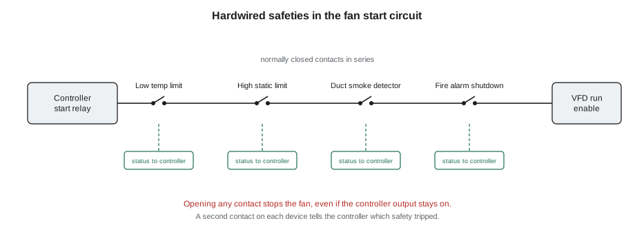
A safety is a protection that acts on its own, without waiting for the program. The standard rule is that safeties which protect people or equipment from serious harm are wired directly into the motor starter or the VFD's safety input, so that they stop the fan even if the controller has failed, is being reprogrammed or has a logic error. The controller monitors each safety through a separate input so that it can report the trip, but the trip itself does not depend on the controller.
| Safety | What it protects | Typical action | Reset |
|---|---|---|---|
| Low temperature limit (freezestat) | Coils from freezing | Stop fan, close outdoor damper, open heating valve | Manual or automatic, as the sequence says |
| High static pressure limit | Ducts and dampers from overpressure | Stop fan | Manual |
| Duct smoke detector | Occupants from smoke spread | Stop fan or go to smoke mode, signal fire alarm | At the fire alarm panel |
| Fire alarm shutdown or smoke control | Occupants | As the fire safety plan requires | At the fire alarm panel |
| VFD fault | The drive and motor | Drive stops itself | At the drive or remotely |
The low temperature limit deserves the most care in a cold climate. A capillary-type limit thermostat stretched across the face of the coil trips when any short section of its element falls below its setting, commonly a few degrees above freezing, such as 3 °C. Its action is to stop the fan and close the outdoor damper through the hardwired circuit, and the sequence then adds software actions: open the heating valve fully, start the hot water pump if it is not running, and raise a critical alarm. Many sequences also include a software low limit on the mixed air or discharge air temperature that acts earlier and more gently, opening the heating valve before the hardwired limit trips.
Three weeks after Sophie's session, on Wednesday, October 7, Callie found what a missing hardwired limit looks like. AHU-2's freezestat at Tilden was wired only to a controller input, and the program waited 15 minutes before acting on it. A frozen coil can split in less time than that. Prakash had it rewired into the fan circuit the same day. The sequence for AHU-2 had always said "hardwired", and the 2009 conversion simply had not followed it.
Smoke and fire alarm interfaces
Air handlers above a certain size have duct smoke detectors, required by the building code to stop the unit or put it into a smoke control mode when smoke is detected in the supply or return air. The detectors belong to the fire alarm system, and the interface with the air handler is defined by the fire safety design, not by the controls contractor. The controls sequence should say what the unit does when it receives a fire alarm signal and must not contradict the fire alarm sequence of operation. Testing these interfaces is coordinated with the fire alarm contractor, as BAS-340 describes.
Ninefield's 1998 penthouse sequence was a good example of an interface described properly. It listed, for each of its four air handlers, the fire alarm input that stopped the unit, the smoke control mode that the fire alarm panel could command instead, and a note that the controls program must not restart the fan while the fire alarm input was active, whatever its schedule said. Sophie pointed out the last sentence. Without it, a program could restart a unit the fire alarm panel had just stopped.
Manual and hand operation
Most motor starters and VFDs have a hand-off-auto selector. In auto, the controller starts the equipment; in hand, it runs regardless of the controller; in off, it does not run at all. A good sequence says that hardwired safeties remain active in hand, and that the controller raises an alarm when the status shows the equipment running without a command, which is how an operator learns that someone left a fan in hand. The same idea, a command and a status that disagree, catches belts, contactors and drives that fail in the other direction.
Restart after a power failure
When power returns after an outage, every controller restarts at once. If every air handler in a building starts immediately, the combined inrush current can trip breakers or the main service, and the building's electrical demand peaks. Sequences therefore require staggered restarts: each unit waits a different delay before starting. BAS-220's alarm flood, 140 restart alarms times three at Ninefield, was another reason to manage restarts carefully.
Worked problem
Staggering restarts after a power failure
Ninefield has 4 penthouse air handlers and 4 rooftop units. The sequence requires the penthouse units to restart 30 seconds apart, starting 60 seconds after power returns, and the rooftop units to restart 20 seconds apart after the last penthouse unit. When does the last rooftop unit start?
Show solution
- Penthouse units start at 60, 90, 120 and 150 s.
- Rooftop units start 20 s after the last penthouse unit: 170, 190, 210 and 230 s.
Answer: The last rooftop unit starts 230 seconds, just under 4 minutes, after power returns. Each unit then runs its own start sequence of about two minutes, so the building is back in control within about six minutes, with no two fans starting in the same 20 seconds.
Common mistakes
MistakeStarting the fan before the dampers have moved.
InsteadCommand dampers first and start the fan on end switch proof or after the actuator stroke time.
MistakeWaiting forever for proof with no alarm.
InsteadCommand the equipment off and alarm if proof does not arrive within the sequence's time.
MistakeWiring a freezestat only to a controller input.
InsteadWire it into the fan's start circuit and monitor it through a separate input.
MistakeLetting the program restart a fan that the fire alarm stopped.
InsteadBlock every start while the fire alarm input is active.
MistakeRestarting every unit at once after an outage.
InsteadStagger restarts with a different delay for each unit.
Summary and key terms
- A start sequence moves dampers first, starts the fan, proves it, and only then enables the loops.
- Proof uses a separate input; each proof device proves something different and can be fooled in its own way.
- A sequence must say what happens when proof fails, usually stop, alarm and wait for reset.
- Stopped positions should agree with fail positions, with special care for the heating valve in cold weather.
- Safeties that protect people and equipment are hardwired into the start circuit and monitored by the controller.
- The controls sequence must respect the fire alarm interface and never restart a unit the fire alarm has stopped.
- Staggered restarts after a power failure limit inrush and alarm floods.
- Proof
- Confirmation from a separate input that equipment responded to its command.
- Start sequence
- The ordered steps that bring equipment from off to normal control.
- Low temperature limit
- A safety that stops an air handler before its coils can freeze; often called a freezestat.
- High static limit
- A safety that stops a fan when duct pressure exceeds a safe value.
- Hardwired safety
- A protection wired directly into a starter or drive circuit so that it acts without the controller.
- Hand-off-auto
- A selector that runs equipment from the controller, manually, or not at all.
- Staggered restart
- Restarting equipment one unit at a time after a power failure.
- Fail position
- The position a device reaches on its own when control power is lost.
Practice problems
Work each problem on paper first, then reveal the answer to check.
An actuator strokes in 90 s, the fan proves 15 s after its command, and loops wait 30 s after proof. When do the loops start?
Show answer
90 + 15 + 30 = 135 s after the start command.
What can fool a current switch used as fan proof?
Show answer
A broken belt, because the motor still draws current.
Why is a freezestat wired into the fan circuit rather than only into the controller?
Show answer
So it stops the fan even if the controller has failed or has a logic error.
What should a program do with a fan's schedule while a fire alarm input is active?
Show answer
Ignore it; the fan must not restart until the fire alarm input clears.
Six units restart 30 s apart, the first 60 s after power returns. When does the last one start?
Show answer
60 + 5 × 30 = 210 s.
Lesson quiz · 5 questions
Score 60% or more to complete this lesson.
Create a free account to save your progress, take quizzes and earn a certificate.