
ARCH-130 · Lesson 2 of 12 · 21 min
Loads and load paths
Back at the Portage Avenue site, Professor Lindqvist stands under the concrete podium and points up. 'Everything above us is pushing down on that slab,' she says. 'Four floors of apartments, their walls and floors, their furniture, the people in them, the snow on the roof in February. Now tell me where it goes.' Ingrid follows the lines with her finger: from the wood studs of the upper floors to a thick transfer beam in the slab, down a concrete column, into the ground. Joon-ho asks what happens when the wind blows. 'Good question,' Lindqvist says. 'Gravity is only half the story.'
What a load is
A load is any force or action that a structure must resist. Loads cause stresses in structural members, which bend, compress, stretch or twist them, and cause movements, which must be kept small enough not to crack finishes, jam doors or alarm the people inside. The first task of structural design is to identify all the loads a building will carry during its life and to trace how each one travels through the structure to the ground.
Loads are usually grouped by their source and by how they act. Gravity loads act downward. Lateral loads act sideways, mainly from wind and earthquakes. Some loads are permanent, some vary over time, and some are rare but severe.
Dead loads
Dead loads are the weight of the building itself: the structure, the floors, roofs and walls, the finishes, the permanent partitions and the fixed equipment. They act all the time and can be estimated fairly accurately from the sizes and densities of the materials. A designer adds them up layer by layer.
| Material or assembly | Typical weight |
|---|---|
| Wood-frame floor with subfloor and drywall ceiling | 0.5 kPa (10 psf) |
| Concrete slab 200 mm (8 in) thick | 4.8 kPa (100 psf) |
| Wood-frame roof with asphalt shingles | 0.6 kPa (12 psf) |
| Clay brick veneer 90 mm (3.5 in) thick | 1.9 kPa (40 psf) of wall face |
| Steel deck with concrete topping, 140 mm (5.5 in) total | 2.5 kPa (50 psf) |
| Normal-weight concrete | 24 kN/m³ (150 lb/ft³) |
| Softwood lumber | 5 kN/m³ (30 lb/ft³) |
The table shows why material choice matters so much. A concrete slab weighs about ten times as much as a wood floor, so a concrete building needs bigger columns and foundations. One reason mass timber and light wood frames are attractive for mid-rise buildings is that they are light, which saves on foundations, especially on the soft clays of the Red River valley.
Live loads
Live loads are the loads from use and occupancy: people, furniture, stored goods, movable equipment and vehicles. They vary over time and are hard to predict, so the code specifies minimum values for each use, based on surveys and experience. The National Building Code sets a uniform live load of 1.9 kPa for floors in dwellings, 2.4 kPa for offices above the ground floor and 4.8 kPa for assembly areas without fixed seats, such as dance floors and gyms, where crowds can pack in. Storage areas, libraries and mechanical rooms carry more. The code also requires checking concentrated loads, such as a heavy safe or a car wheel, which can punch through a floor even when the uniform load is modest.
Live loads are lower than you might expect because they are spread over a whole floor. A crowded room of people standing close together weighs only about 4 to 5 kPa (80 to 100 psf). But they are uncertain, so they are multiplied by larger safety factors than dead loads in design.
Snow and rain loads
In a northern climate, snow is often the largest load on a roof. The National Building Code gives a ground snow load and an associated rain load for each location in its climatic tables, based on decades of weather records; for Winnipeg the values are roughly 1.9 kPa and 0.2 kPa. The roof load is calculated from the ground load by multiplying by factors for the size of the roof, wind exposure, slope and shape, and adding the rain that can soak into the snow. A small sheltered roof carries about 80% of the ground snow load, a large roof more, and a steep, slippery roof less. Snow also drifts: wind blows it off high roofs onto lower ones and piles it against parapets and rooftop equipment. Drifts can be several times deeper than the average snow, and many roof collapses happen at a step in the roof where a drift was not designed for.
Wind loads
Wind pushes on the windward face of a building and pulls on the leeward face and on the roof, where the air speeds up and the pressure drops. The suction on a roof can be large enough to lift it off if it is not tied down, which is why hurricane straps connect rafters to walls in windy regions. Wind pressure grows with the square of the wind speed, so a wind twice as fast pushes four times as hard.
For a wind speed of 30 m/s (67 mph), this gives a velocity pressure of about 0.56 kPa (12 psf). The code adjusts this reference pressure for height, terrain, gusts and the shape of the building. Tall buildings, buildings on open terrain and buildings near the edge of a lake or prairie see higher pressures. Corners and roof edges see the strongest suction, so cladding and roofing are fastened more closely there.
Earthquake and other loads
Earthquakes shake the ground, and the building's mass resists the motion, producing sideways inertia forces in the structure. The force depends on the mass of the building, the intensity of shaking expected at the site and the flexibility and ductility of the structure. Heavy buildings attract larger earthquake forces, another advantage of light construction. Winnipeg has very low seismic hazard, but Vancouver, Victoria and Montréal do not, and the same building design can need very different lateral systems in different places.
Other loads include the pressure of soil and water on basement walls, thermal expansion and contraction, the shrinkage of concrete and wood, ice on structures, impact from vehicles, and loads during construction, when a partly built frame may be at its weakest. On a riverbank such as Kestrel Point, flood water and ice add their own pressures.
Load combinations and safety
Loads do not all reach their maximum at once. A building is unlikely to be fully loaded with people, under the heaviest snow of fifty years, in the strongest wind and during an earthquake all at the same time. Codes therefore specify load combinations: sets of loads multiplied by load factors, which are larger for uncertain loads and smaller for well-known ones. In the NBC, a common combination is 1.25 times the dead load plus 1.5 times the live load plus 0.5 times the snow load; another is 1.25 dead plus 1.5 snow plus 0.5 live. The structure is then designed so that its factored resistance is at least equal to the largest factored load effect. This approach is called limit states design, or load and resistance factor design.
The factors build in a margin of safety. They cover uncertainty in loads, in material strength, in workmanship and in the models engineers use. A structure designed this way has a very low probability of failure in its life, but not zero.
The load path
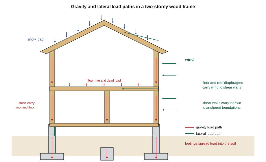
A load path is the route a load takes from where it is applied, through the structural members, to the ground. Every load must have a complete, continuous load path; if one link is missing, the load will find another route, perhaps through a partition or a window frame that was never meant to carry it, or the structure will fail.
For gravity loads in a typical wood-frame house, the path runs: from the roof sheathing to the rafters or trusses; from the trusses to the top plates of the walls; down the studs to the bottom plate and the floor below; through the floor framing to the foundation wall; down the foundation wall to the footing; and from the footing into the soil. Where an opening interrupts a wall, a header carries the load over it to the studs at each side. Where a wall above does not sit on a wall below, a beam must pick up its load, a transfer.
For lateral loads, the path runs: from the wall cladding to the studs; from the studs to the floor and roof, which act as horizontal deep beams called diaphragms; from the diaphragms to the shear walls or braced frames that resist sideways forces; and down those walls to the foundations, which must be anchored against sliding and overturning. The sheathing on walls and floors is not just a backing for cladding but a structural part of the lateral system, which is why it is nailed in a specific pattern.
Tributary areas
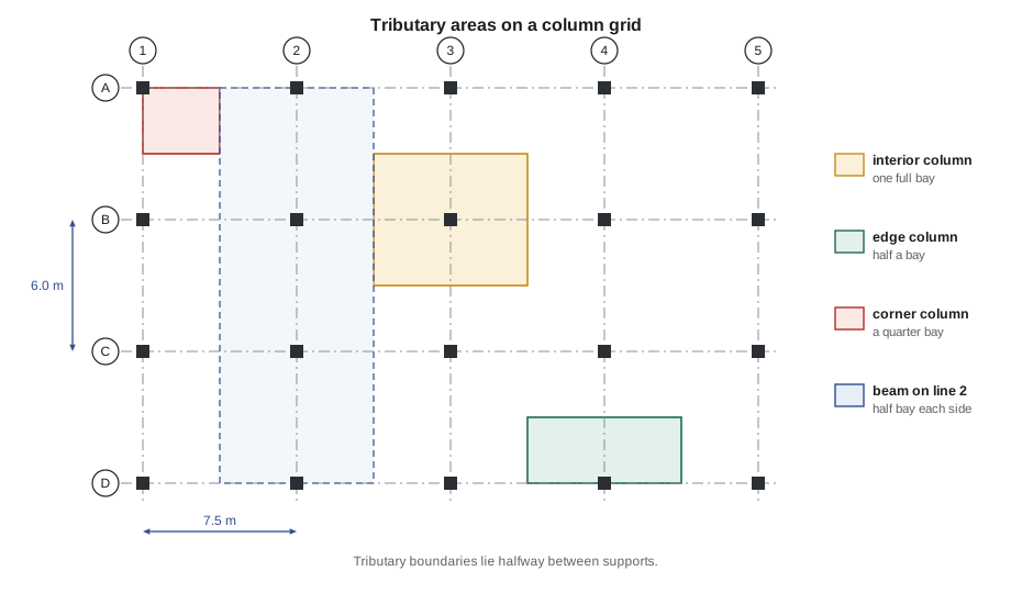
To find the load on a beam or column, designers use the idea of a tributary area: the area of floor or roof whose load flows to that member. For a beam supporting a floor, the tributary width is half the distance to the next beam on each side. For an interior column in a regular grid, the tributary area is a rectangle extending halfway to the neighbouring columns in each direction. An edge column has about half the area of an interior column, and a corner column about a quarter.
# Load on an interior column of the podium, one floor, limit states (NBC-style factors)
bay_x, bay_y = 6.0, 7.5              # m, column spacing in each direction
area = bay_x * bay_y                 # tributary area of an interior column, m2
dead = 0.5 + 1.0                     # kPa: wood floor plus partitions and finishes
live = 1.9                           # kPa: residential floor
factored = 1.25 * dead + 1.5 * live  # kPa
floors = 4
P = factored * area * floors
print(f"Tributary area = {area:.1f} m2")
print(f"Factored floor load = {factored:.2f} kPa")
print(f"Load on the column from {floors} floors = {P:.0f} kN")Tributary area = 45.0 m2 Factored floor load = 4.72 kPa Load on the column from 4 floors = 850 kN
This simple estimate ignores the roof and the reduction codes allow for live loads on large areas, which are unlikely to be fully loaded at once, but it gives the right order of magnitude, which is what an architect needs to judge whether a column on the drawings is plausible.
Worked problem
Tracing the load path through the boathouse
Callum's boathouse has rafters at 600 mm (24 in) spacing spanning from a ridge beam to the side walls, the ridge beam is carried by a post at each gable end, and the side walls stand on a timber floor supported by beams on concrete piers. Where does the snow on the roof go?
Show solution
- Snow presses on the roof sheathing, which spans between rafters.
- Each rafter carries a strip of roof 600 mm (24 in) wide. Half of its load goes to the ridge beam and half to the side wall.
- The ridge beam carries the upper halves of all the rafters and delivers its load to the two gable posts. Each post therefore carries a quarter of the whole roof.
- The side walls carry the lower halves of the rafters down their studs to the floor beams, which take the load to the piers.
- The gable posts must sit directly on a pier or on a beam that is strong enough for a concentrated load.
Answer: Because the ridge beam is structural, the gable posts carry large point loads, and the piers under them must be bigger than the others. If the ridge were only a board and the rafters were tied at their feet, the roof load would go to the side walls instead.
Exercise 2: drawing a load path
This exercise takes about three hours.
- Take a section drawing of a small building you have designed, such as the boathouse, or one from a published set of drawings.
- In red, draw arrows tracing gravity loads from the roof and each floor to the soil. Mark every transfer, where a load moves sideways to get around an opening or a change in the wall layout.
- In blue, trace a wind load from the side wall to the foundations, through the diaphragms and shear walls.
- Estimate the tributary area and the dead, live and snow loads on the most heavily loaded post or column.
- Deliverable: the annotated section, a short load calculation and a note on any weak link you found.
Self-critique checklist
- Does every arrow reach the ground without a gap?
- Have I traced lateral loads as well as gravity loads?
- Have I identified the transfers and point loads?
- Are my load values from a reliable source, with units?
Common mistakes
MistakeTracing only gravity loads.
InsteadWind and earthquake loads need their own continuous path through diaphragms and shear walls.
MistakeAssuming a wall above can sit anywhere.
InsteadA wall or post that does not line up with one below needs a beam to transfer its load.
MistakeForgetting snow drifts.
InsteadDrifts at steps, parapets and equipment can be several times the average roof snow.
MistakeTreating sheathing as cosmetic.
InsteadNailed sheathing makes walls and floors work as shear walls and diaphragms.
Summary and key terms
- Dead loads are the weight of the building; live loads come from use and occupancy.
- Snow is often the largest roof load in a northern climate, and drifts concentrate it.
- Wind and earthquakes produce lateral loads that need their own load path.
- Codes combine loads with load factors, and structures are designed for the worst combination.
- Every load needs a continuous path to the ground; tributary areas show how much each member carries.
- Dead load
- The permanent weight of the structure, finishes and fixed equipment.
- Live load
- The variable load from people, furniture and movable contents.
- Load path
- The route by which a load travels through the structure to the ground.
- Diaphragm
- A floor or roof that acts as a horizontal beam to carry lateral loads to the walls.
- Tributary area
- The area of floor or roof whose load is carried by a particular beam or column.
Practice problems
Work each problem on paper first, then reveal the answer to check.
What is the difference between a dead load and a live load?
Show answer
Dead loads are permanent weights of the building; live loads come from use and vary over time.
Why are snow drifts dangerous?
Show answer
They pile snow far deeper than the average at roof steps and parapets, and can exceed the design load if ignored.
If wind speed doubles, what happens to wind pressure?
Show answer
It increases about four times, because pressure depends on the square of the speed.
A floor beam is midway between two others, each 3 m (10 ft) away. What is its tributary width?
Show answer
Half of each spacing on either side: 1.5 m + 1.5 m = 3 m (5 ft + 5 ft = 10 ft).
What is a transfer?
Show answer
A beam or other member that picks up a load from above and carries it sideways to supports that do not line up with it.
Lesson quiz · 5 questions
Score 60% or more to complete this lesson.
Create a free account to save your progress, take quizzes and earn a certificate.