
ARCH-130 · Lesson 12 of 12 · 21 min
Reading construction drawings
On the last visit to the Portage Avenue site, the superintendent invites the class into the site trailer. Pinned on one wall is a full set of drawings, more than a hundred sheets, and on a table lies a thick binder of specifications. He opens the set to a wall section and puts his finger on a small circle with a number and a letter in it. 'Detail 7 on sheet A-502,' he says, flipping a dozen pages. 'There it is, the window head. My framer, my window installer and my siding crew will all look at this drawing. If it is unclear, they will each do it their own way, and I will be fixing it in a year.' He points to a stack of paper beside the binder. 'Those are questions we have sent the architect since we started. Every one is a place where the drawings did not say enough.' Ingrid counts more than two hundred.
Construction documents
A building is built from a set of construction documents prepared by the architect and the engineers. They have two main parts. The drawings show the geometry, location, size and arrangement of everything: what goes where. The specifications describe the quality of materials and workmanship, the products, standards, tests and procedures: what it is and how it is done. Together with the contract between the owner and the builder, they form the legal basis for construction, and if there is a dispute, the documents decide who is responsible. A good set is complete, consistent, clear and coordinated between disciplines.
Drawings are organized by discipline, each with a letter prefix: G for general, C for civil, L for landscape, A for architectural, S for structural, M for mechanical, P for plumbing, E for electrical and FP for fire protection. Within each discipline, sheets are numbered in a logical order: in the US National CAD Standard, which is also widely used in Canada, A-101 is the first floor plan, A-201 the first elevation sheet, A-301 the first sections, A-501 the first details and so on. Every sheet has a title block giving the project, the sheet name and number, the date, the scale, the firm and the seal or stamp of the responsible professional, and a revision block recording every change after the drawings are issued.
Types of drawings
The architectural drawings move from the general to the particular, as you learned in ARCH-110.
- The site plan shows the building on its property: property lines, setbacks, existing and new grades, paving, landscaping, utilities and the north arrow.
- Floor plans are horizontal cuts, usually about 1.2 m (4 ft) above the floor, showing walls, doors, windows, stairs, fixtures, dimensions and tags that refer to schedules and details.
- The reflected ceiling plan shows the ceiling as if reflected in a mirror on the floor: ceiling heights, materials, lights, diffusers and sprinklers.
- Exterior elevations show the faces of the building with materials, openings, heights and levels.
- Building sections are vertical cuts through the whole building, showing floor-to-floor heights and the relationship of spaces.
- Wall sections are larger-scale vertical cuts through the envelope, from foundation to roof, showing every layer, as in the exercises of lessons 5 and 9.
- Details are large-scale drawings of specific conditions, such as a window head, a roof edge, a stair nosing or a joint.
- Schedules are tables listing doors, windows, finishes, equipment and their properties, keyed to tags on the plans.
The engineers' drawings follow the same pattern: foundation and framing plans with member sizes and details for structure; plans, riser diagrams and schedules for mechanical, plumbing and electrical systems. A reader must often move between sheets and disciplines to understand one condition: a wall on the architectural plan, its footing on the structural foundation plan, the duct that passes through it on the mechanical plan.
Scales
Each type of drawing has a conventional scale.
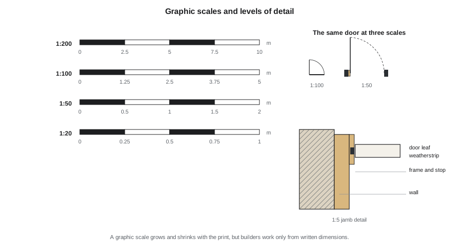
Canadian drawings use metric ratio scales, with dimensions in millimetres: site plans at 1:500 or 1:200, floor plans, elevations and sections at 1:100 or 1:50, wall sections at 1:20 or 1:10, and details at 1:10, 1:5 or even 1:1. Some residential drawings in Canada are still drawn in imperial units, so check the title block.
Drawings printed at a different size from the one they were drawn for are no longer to scale, which is why sheets carry a graphic scale bar that grows and shrinks with the print, and why builders are told never to scale a drawing to find a dimension: if a dimension is not written, they ask.
# Converting between drawing measurements and real sizes at metric scales
def real_size(measured_mm, scale):
    return measured_mm * scale            # mm in reality

def drawn_size(real_mm, scale):
    return real_mm / scale                # mm on paper

print("A 900 mm door at different scales:")
for s in (200, 100, 50, 20):
    print(f"  1:{s:<4d} drawn {drawn_size(900, s):6.1f} mm wide")
print("A 37 mm line on a 1:50 wall section represents", real_size(37, 50), "mm")

# printed at half size (A3 instead of A1-size scale), a 1:100 drawing becomes 1:200
print("1:100 printed at 50% becomes 1:", int(100 / 0.5))A 900 mm door at different scales: 1:200 drawn 4.5 mm wide 1:100 drawn 9.0 mm wide 1:50 drawn 18.0 mm wide 1:20 drawn 45.0 mm wide A 37 mm line on a 1:50 wall section represents 1850 mm 1:100 printed at 50% becomes 1: 200
Line types and symbols
Construction drawings use a conventional language of lines and symbols, much of it learned in ARCH-110 but now used with precise meaning. Line weights show depth: elements cut by the plane of a plan or section are drawn heaviest; elements seen beyond are thinner; dimensions and notes are finest. Line types show meaning: solid lines for visible edges, dashed lines for hidden elements or things above the cut, such as a roof overhang on a plan, long chain lines for grid lines and centrelines, and long and two short dashes for property lines.
Materials cut in section are filled with hatching, conventional patterns that identify them at a glance: diagonal lines for brick, a stipple of dots and triangles for concrete, a wavy pattern for batt insulation, a cross pattern for rigid insulation, an X or grain lines in a box for wood, and crosshatching or dots for earth and gravel. The patterns vary slightly between offices, so every set has a legend.
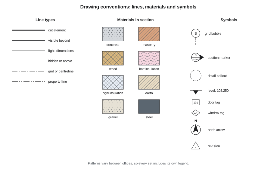
Symbols connect the drawings together. Grid lines, labelled with numbers in one direction and letters in the other in circles called grid bubbles, locate the structure and everything else; dimensions are usually taken from them. Section markers on a plan show where a section is cut, with arrows for the direction of view, and a circle giving the section number and the sheet on which it is drawn. Detail callouts, circles or bubbles around part of a drawing, refer to an enlarged detail elsewhere. Elevation markers show the direction of interior elevations. Level symbols give the height of floors and other elements above a datum. Door and window tags refer to the schedules. A north arrow orients each plan.
Dimensions and levels
Dimensions locate and size everything. They are arranged in strings, from the overall dimension on the outside to smaller ones nearer the building, and they are taken from consistent reference points: grid lines, the face of the structure or the face of the framing. Office practice varies on whether walls are dimensioned to the face of stud, the centre of the stud or the finished surface, so the convention must be stated. In metric drawings, dimensions are written in millimetres without a unit, such as 3600, and levels in metres to three decimals, such as 103.250.
Dimensions should be complete, so a builder never has to add or subtract to find one, and not duplicated, because duplicated dimensions can disagree when one is revised. Critical dimensions, such as clear widths of corridors, stairs and accessible routes, are noted as clear or minimum, so the builder knows they cannot shrink.
Specifications
Specifications are written documents organized by a standard system. In Canada and the United States, the usual system is MasterFormat, published by the Construction Specifications Institute and Construction Specifications Canada, which divides construction into numbered divisions. Division 03 covers concrete, 04 masonry, 05 metals, 06 wood, plastics and composites, 07 thermal and moisture protection, 08 openings (doors and windows), 09 finishes, 21 fire suppression, 22 plumbing, 23 HVAC and 26 electrical. Each section is usually written in three parts: general requirements, such as submittals and quality control; products, the materials and manufacturers; and execution, how the work is installed and tested.
The drawings and specifications must agree. A note on the drawing should name the material, such as rigid mineral wool insulation, and leave the product properties, thickness standards and installation requirements to the specification, rather than repeating them in two places where they might conflict. Many contracts state which governs if they do.
From documents to building
Construction documents do not end the architect's involvement. During construction, the contractor and suppliers prepare shop drawings, detailed drawings of fabricated items such as steel, trusses, windows, curtain walls and millwork, and submit them with product data and samples for the architect and engineers to review. When the documents are unclear or conflict with conditions on site, the contractor sends a request for information (RFI), as in the superintendent's stack. Changes to the work are made by formal change orders, which adjust the price and schedule. The architect visits the site to observe the work and report on whether it follows the documents. At the end, the contractor provides record drawings, often called as-builts, showing what was actually built, which are invaluable to everyone who later maintains or renovates the building.
How to read a set
Reading a set of construction drawings is a skill learned by practice. A useful sequence is this.
- Start with the cover sheet and the general notes, the drawing list, the legend of symbols and abbreviations, and the code summary, which states the building's classification, area, height, construction type and fire ratings.
- Read the site plan and the floor plans to understand the building as a whole: its shape, grid, levels and main spaces.
- Read the elevations and building sections to understand its heights and how the floors relate.
- Follow one condition through the set: pick a wall on the plan, follow its section marker to the wall section, its detail callouts to the details, and its tags to the schedules. Then find the same wall on the structural and mechanical drawings.
- Read the specification sections for the materials you have found.
- Note every question or conflict. That is what an RFI is, and finding them before construction is the best use of a reader's time.
Worked problem
Following the boathouse window head through a set
Callum has drawn a small set for the warming hut: a plan, two elevations, a section, a wall section and details. A builder asks how the window head is built. Which drawings answer the question?
Show solution
- The plan shows the window tag, W1, and a section marker through the long wall, numbered 1 on sheet A-301.
- The window schedule gives W1's size, type, glazing and frame material.
- Section 1 on A-301 shows the window in the wall and a detail callout at the head, numbered 3 on sheet A-501.
- Detail 3 on A-501 shows the header, the head flashing, the water-resistive barrier lapped over it, the cavity, the trim and the air seal at 1:5 (3 in = 1 ft).
- The specification sections for windows, flashing and air barriers give the products and installation requirements.
Answer: The question is answered by the plan, the schedule, the wall section, the head detail and the specifications together. If any of these were missing or disagreed, the builder would send an RFI.
Exercise 12: a small construction set
This final exercise draws on the whole course and takes about two weeks.
- Produce a small set of construction drawings for the boathouse converted into a heated warming hut: a site plan, a floor plan, a roof plan, two elevations, a building section, a wall section from footing to roof, and at least four details: the pile and floor connection, the eave, a window head and sill, and the door threshold.
- Include a title block, sheet numbers, a legend, grid lines, section markers, detail callouts, a door and window schedule and general notes.
- Show the load path, the control layers and the services on the appropriate drawings, as in lessons 2, 9 and 11.
- Write a one-page outline specification listing the main products in MasterFormat divisions.
- Deliverable: the set, at the scales of this lesson, and the outline specification.
Self-critique checklist
- Can a builder find every condition by following callouts from the plan?
- Are all critical dimensions written, so nothing has to be scaled?
- Are the four control layers continuous in the wall section and details?
- Do the drawings and specifications agree?
Common mistakes
MistakeScaling a drawing to find a missing dimension.
InsteadNever scale; write every dimension a builder needs, and ask when one is missing.
MistakeRepeating the same information on drawings and specifications.
InsteadPut geometry on the drawings and quality in the specifications to avoid conflicts.
MistakeDrawing details that do not match the wall sections.
InsteadCoordinate callouts and details so each condition is shown once, consistently.
MistakeTreating construction documents as the end of the job.
InsteadShop drawings, RFIs, site visits and record drawings continue the architect's work.
Summary and key terms
- Construction documents are drawings, which show what goes where, and specifications, which describe quality and workmanship.
- Drawings are organized by discipline and sheet number and move from site plan to details.
- Each drawing type has a conventional scale; builders work from written dimensions, never by scaling.
- Line types, hatches and symbols, such as grid bubbles, section markers and callouts, connect the set together.
- Specifications follow MasterFormat; shop drawings, RFIs and change orders carry the documents into construction.
- Construction documents
- The drawings and specifications from which a building is built.
- Detail callout
- A symbol that refers to an enlarged drawing of part of another drawing.
- Schedule
- A table of doors, windows, finishes or equipment keyed to tags on the drawings.
- MasterFormat
- The standard system of numbered divisions used to organize specifications.
- RFI
- Request for information: a question from the contractor about the documents.
Practice problems
Work each problem on paper first, then reveal the answer to check.
What is the difference between the drawings and the specifications?
Show answer
Drawings show geometry and arrangement; specifications describe materials, quality and workmanship.
What does a section marker on a plan tell you?
Show answer
Where a section is cut, the direction of view, and the number and sheet of the section drawing.
Why should builders never scale a drawing?
Show answer
Prints may not be at their intended size, and written dimensions are the binding information.
Which MasterFormat division covers doors and windows?
Show answer
Division 08, openings.
What are record drawings?
Show answer
Drawings prepared at the end of construction showing what was actually built.
Lesson quiz · 5 questions
Score 60% or more to complete this lesson.
Create a free account to save your progress, take quizzes and earn a certificate.