
APP-320 · Lesson 6 of 12 · 26 min
Brushless DC and inverter motors
▶ Video coming soon A video version of this lesson is on the way.
Ines brought the cut-away washer to the front of the room for this session. Its back was open to show a large flat stator bolted to the rear of the tub and, around it, a steel dish lined with magnets, the rotor, fixed straight onto the drum shaft. There was no belt and no pulley. Dee used it to tell her case from Wednesday, September 2: Saoirse Delahunt in Meadowlands had a front-loader that filled and tumbled weakly, then stopped every cycle with the sample code F51, motor did not reach commanded speed. The drum turned freely by hand, so it was not seized. The stator's three windings measured an equal 7.4 Ω between each pair. But in the service mode's motor test, the speed shown stayed at zero while the drum turned. At the stator, one of the five pins in the Hall sensor connector had backed out of its housing, so one sensor's signal never reached the board. Dee re-seated the terminal with the maker's tool, locked the connector's secondary latch and ran a spin test to 1,200 rpm.
This lesson explains brushless DC motors and the inverter or motor control boards that run them in washers, dryers, dishwashers and refrigerator fans; how they sense the rotor's position; how direct-drive washer motors are built; and how to test stators, rotors, Hall sensors and the boards that drive them, safely and without guessing.
From brushes to brushless
The laundry course described the motors older washers used: PSC induction motors with a run capacitor, running at a fixed speed and needing a transmission or two speeds of windings, and universal motors with brushes, whose speed the board could vary by controlling the voltage through a triac and measuring speed with a tachometer. Universal motors made variable spin speeds possible but wore out their brushes and were noisy.
A brushless DC (BLDC) motor, also called an ECM (electronically commutated motor) or a permanent-magnet synchronous motor, does the same job with no brushes at all. Its rotor carries permanent magnets. Its stator carries windings, usually three sets or phases. Instead of brushes switching the current through the windings as the rotor turns, a motor control board, an inverter like the one in lesson 5, switches the current electronically in the right sequence. The motor is efficient, quiet and reversible, and its speed and torque can be set very precisely. That makes it ideal for washers that tumble at 40 rpm and spin at 1,400 rpm, for dishwasher wash pumps that change pressure through a cycle, and for refrigerator and condenser fans that must run at many speeds for little power.
Direct-drive washer motors
In a direct-drive washer, the BLDC motor is built around the drum shaft. The stator, a ring of laminated steel with many teeth, each wound with copper wire, is bolted to the outer tub. The rotor, a steel dish with a ring of magnets inside its rim, is fixed to the drum shaft by a single central bolt and turns around the stator. Because the motor turns the drum directly, there is no belt or transmission to wear. Most designs have a Hall sensor assembly mounted on the stator, where it reads the rotor's magnets as they pass; some newer designs are sensorless and read the rotor's position from the back-EMF in the windings, as inverter compressors do.
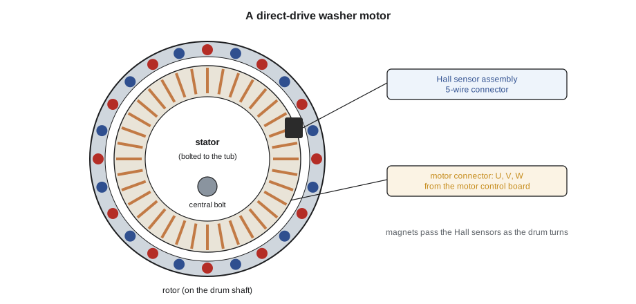
The motor control board, either a separate inverter board or a section of the main board, makes three-phase power at a variable frequency from a DC bus, exactly as for a compressor. It reads the Hall sensors to know where the rotor is, switches the windings to pull the rotor round, and counts the sensor pulses to measure speed. During spin it can also sense out-of-balance loads by the way the speed rises and falls, and it brakes the drum electronically at the end of the spin.
Worked problem
How fast the motor control switches
A direct-drive rotor has 36 magnet poles, which is 18 pole pairs. The electrical frequency the board must produce equals the speed in rpm times the pole pairs, divided by 60. What frequency does the board produce at a tumble speed of 50 rpm and a spin of 1,200 rpm?
Show solution
- At 50 rpm:
- \[f = \frac{50 \times 18}{60} = 15 \text{ Hz}\]
- At 1,200 rpm:
- \[f = \frac{1{,}200 \times 18}{60} = 360 \text{ Hz}\]
Answer: From about 15 Hz in a wash to about 360 Hz in a spin (for this sample motor). The board, not the household supply, sets the frequency, which is why the motor leads cannot be checked against a fixed voltage or frequency while running.
Sensing the rotor
A typical Hall sensor assembly holds three Hall sensors spaced around a few teeth of the stator, plus supply and common wires, giving a connector with five wires (typical). Each sensor's output switches high and low as the rotor's north and south poles pass. Together, the three outputs form a pattern that tells the board which pair of windings to energize next and in which direction the rotor is turning. If one sensor is missing, the pattern is incomplete: the board may start the motor weakly, run it roughly, or fail to reach speed and stop with a speed fault, as Saoirse Delahunt's washer did. If all three are missing, the board usually cannot start the motor at all.
To test a Hall sensor assembly, the machine is powered with the connector plugged in, normally in the service mode or with the board idle, and each output is measured to common on DC volts while the drum is turned slowly by hand. Each output should switch between about 0 V and close to the supply voltage, often 5 V or 12 V (typical), as the rotor moves. A sensor that stays high or low while the others switch has failed or lost its connection. The tech sheet gives the pins and the expected voltages. Measure at the back of the connector without forcing probes into the terminals, which can spread them and cause the very fault being looked for.
| Check | How | Expected (typical) |
|---|---|---|
| Stator windings | Power off; three-pin connector unplugged; ohmmeter U–V, V–W, W–U | Three equal readings, a few ohms to about 15 Ω; see the tech sheet |
| Stator insulation | Power off; each pin to the tub or a ground point | Very high, many megohms |
| Hall sensor supply | Powered, connected; supply pin to common | About 5 V or 12 V, as the tech sheet says |
| Hall sensor outputs | Powered, connected; turn drum slowly; each output to common | Each switches between about 0 V and the supply |
| Rotor | Visual, power off | Magnets intact and bonded, no rubbing marks, bolt tight |
| Speed readout | Service mode motor test | Speed follows the command; no speed fault |
Testing the stator and rotor
The stator is tested like an inverter compressor. With the washer unplugged and the motor control board's bus measured near zero, the three-pin motor connector is unplugged and the resistance measured between each pair of pins. The three readings should be equal; the tech sheet gives the value, often a few ohms to about 15 Ω (typical). An open reading means a broken winding or lead; unequal readings mean a damaged winding. Then each pin is measured to the tub or a ground point: the reading must be very high. A stator that has had water on it, from a leaking tub seal for example, may read low to ground and will trip the board's protection.
The rotor has no wiring to test, but it can fail mechanically. Its magnets can crack or come loose, its central bolt can loosen, and a failing rear tub bearing can let the rotor rub on the stator. Look for magnet chips in the bottom of the cabinet, scuff marks on the stator teeth and a drum that wobbles. A loose rotor bolt is a common cause of a knocking noise and of speed faults, and it must be tightened to the maker's torque with the right thread locker. A worn bearing is the real fault behind many rubbing rotors, and the laundry course explained how to judge that repair.
Worked problem
Is the stator balanced?
A stator reads 7.4 Ω, 7.4 Ω and 7.5 Ω between its three pairs of pins, and more than 20 MΩ from each pin to the tub. The tech sheet gives about 7.5 Ω per pair. Is the stator good?
Show solution
- The three readings are within 0.1 Ω of each other and of the specification.
- The insulation readings are very high.
Answer: The stator's windings and insulation are good. If the washer still has a speed fault, the Hall sensor assembly, its connector and harness, the rotor and the motor control board are next, in that order.
Generator effect and other cautions
A permanent-magnet motor works as a generator when it is turned. Spinning a direct-drive drum quickly by hand can produce a surprising voltage at the motor's three-pin connector, and if the connector is unplugged and the pins exposed, they can give a shock or arc. Turn the drum slowly when testing, keep the motor connector plugged in or its pins covered, and never spin a drum hard with the motor disconnected and the pins near anything conductive. Some motor control boards use this same effect deliberately to brake the drum.
The motor control board's DC bus is as dangerous as any other. After unplugging, measure it at the tech sheet's test points before touching the board. Keep the motor leads in the correct order when reconnecting; reversed leads make the motor run backward or vibrate. And because motor control boards often sit low in the cabinet, where a leak can reach them, look for water and detergent marks before deciding a board has simply worn out.
BLDC motors elsewhere in the home
Small BLDC motors are everywhere in modern appliances. Dishwasher wash pumps often use one, run by the main board, so the wash pressure can change through the cycle; the dishwasher course described their pumps and spray arms. Refrigerator fans are often 12 V DC brushless fans with two, three or four wires: supply and common, plus a tachometer wire that sends pulses as the fan turns and sometimes a PWM wire that sets the speed. A board that sees no tach pulses from a fan may report a fan fault even though the fan is turning, if the tach wire is broken. A three- or four-wire fan should not be tested by applying a supply directly unless the tech sheet allows it; check the supply voltage the board provides and the fan's tach output instead. Dryer and washer drive motors on some belt-drive machines are BLDC motors in a conventional housing with their own small control board. Range hood blowers, ice maker and dispenser motors are increasingly BLDC as well.
Worked problem
A fan the board thinks has stopped
A refrigerator shows an evaporator fan fault, but the fan can be heard running. The fan is a 12 V DC brushless type with three wires. What should be checked, and in what order?
Show solution
- Confirm the fan turns at normal speed with the door switch pressed, if the model stops the fan with the door open.
- Measure the supply at the fan connector, connected: about 12 V DC, as the tech sheet says.
- Measure the tach wire, connected, while the fan runs: a meter on DC volts shows an average that changes; some meters can read the frequency.
- If the tach wire shows nothing while the fan runs, check its continuity from the fan connector to the board.
Answer: A running fan with no tach signal at the board points to the tach wire, the connector or the fan's internal tach circuit, not to the fan motor or the board. Replace the fan or repair the harness as the measurements show.
Ines finished the session by unplugging the Hall sensor connector on the cut-away washer and running its motor test. The drum lurched, stopped, and the display showed F51. She plugged it back in and the drum spun up smoothly. "Same washer, same board, same motor," she said. "One connector."
Belt-drive BLDC motors and motor control boards
Not every BLDC washer is direct drive. Many top-loaders and some front-loaders use a BLDC motor in a conventional housing, mounted under the tub and driving a pulley through a belt, with the motor control board either mounted on the motor or nearby. The tests are the same: three equal stator readings, a very high reading to ground, Hall sensor outputs that toggle as the pulley is turned slowly, and a speed readout that follows the command. A slipping belt can mimic a motor fault, because the motor reaches its speed but the drum does not; most boards measure the motor's speed, not the drum's, so they may not report it. Watch the drum and the pulley together during a spin test.
Motor control boards have their own protections. They stop the motor and set a fault for overcurrent, an overheated power module, a bus voltage out of range, a locked rotor or an unbalanced load they cannot correct. An overcurrent fault on a machine with a heavy, waterlogged load, a failing tub bearing or a stiff transmission is the board protecting itself, not failing. That is why the drum is always turned by hand and the bearings and belt checked before a motor control board is blamed.
Common mistakes
MistakeReplacing a motor control board for a speed fault without testing the Hall sensors.
InsteadMeasure each Hall output toggling while turning the drum slowly, and check its connector.
MistakeForcing meter probes into connector terminals.
InsteadBack-probe gently or use the maker's test adapter; spread terminals cause intermittent faults.
MistakeSpinning a drum hard with the motor connector unplugged.
InsteadTurn it slowly; a permanent-magnet motor generates voltage when spun.
MistakeTesting a three-wire DC fan by putting 12 V straight on it.
InsteadCheck the board's supply and the tach signal as the tech sheet describes.
MistakeIgnoring a loose rotor bolt or magnet chips.
InsteadInspect the rotor and bearing; mechanical faults cause speed codes and noise.
Summary and key terms
- BLDC motors have permanent-magnet rotors and electronically switched stator windings.
- A motor control board, an inverter, makes variable-frequency three-phase power from a DC bus.
- Direct-drive washers have a stator on the tub and a magnet rotor on the drum shaft.
- Three Hall sensors, or back-EMF sensing, tell the board where the rotor is.
- A missing Hall signal causes weak starts, rough running and speed faults.
- Stators should read three equal resistances and a very high reading to the tub.
- Permanent-magnet motors generate voltage when turned; turn drums slowly.
- Wash pumps, fans and other small motors are increasingly BLDC, with tach and PWM wires.
- Stator
- The fixed part of a motor carrying the windings.
- Rotor
- The turning part of a motor; in a BLDC motor it carries magnets.
- Direct drive
- A washer motor built onto the drum shaft with no belt.
- Hall sensor assembly
- The group of Hall sensors that reads a motor's rotor position.
- Motor control board
- The inverter board that drives a BLDC motor.
- Sensorless motor
- A BLDC motor whose rotor position is read from back-EMF.
- Tachometer wire
- A wire that carries speed pulses from a fan or motor.
- ECM
- Electronically commutated motor, another name for a BLDC motor.
Practice problems
Work each problem on paper first, then reveal the answer to check.
Why does a direct-drive washer have no belt?
Show answer
The motor is built onto the drum shaft.
What do the Hall sensors on a stator tell the board?
Show answer
Where the rotor is and how fast it turns.
How should three stator winding readings compare?
Show answer
They should be equal, matching the tech sheet.
Why turn a direct-drive drum slowly when testing?
Show answer
The permanent-magnet motor generates voltage when spun.
A running DC fan shows a fan fault. What wire should be checked?
Show answer
The tach wire from the fan to the board.
Lesson quiz · 5 questions
Score 60% or more to complete this lesson.
Create a free account to save your progress, take quizzes and earn a certificate.