
APP-320 · Lesson 2 of 12 · 29 min
Power supplies and low voltage circuits
▶ Video coming soon A video version of this lesson is on the way.
Hiro brought the second session of the electronics day to the bench. On Tuesday, October 13, before Kiran started, he had been called to Ignatius Bromley's house in Falkirk, where a two-year-old induction cooktop was completely dead. The breaker was on and the cooktop had 240 V at its terminal block, but nothing on its touch panel lit. Hiro had found the cooktop's small power supply fuse open and, under the board, a cracked filter capacitor near a scorch mark. He did not touch either. He waited, measured the large bus capacitor until it read nearly zero, photographed the board and the scorch, and ordered the maker's power board. "The capacitors on an induction board can hold a dangerous charge after the power is off," he told the group, holding up the old board. "Before your hands go near one, your meter goes on it."
This lesson explains how appliance boards get their low-voltage DC power, how switch-mode supplies work, why large capacitors can stay charged, how to measure supply voltages safely, and how to recognize isolated and non-isolated supplies. It also covers fuses and protective parts and how to tell a failed supply from a fault that is pulling it down.
Why boards need DC
The household supply is alternating current: 120 V between a hot conductor and neutral, and 240 V between two hot conductors for ranges, dryers and some cooktops. A microcontroller cannot run on that. It needs a small, steady direct current voltage, typically 5 V or 3.3 V (typical values). Relay coils, sensors and display backlights often run on 12 V or 15 V DC. Motor drives in inverter compressors, washers and induction cooktops need a much higher DC voltage, called the DC bus, which they switch rapidly to make the power their motor or coil needs. Every electronic appliance therefore has at least one power supply that converts the AC supply into these DC voltages.
Power supplies are of two broad kinds. Older and simpler boards used a linear supply: a small transformer steps the 120 V down to perhaps 12 V AC, a bridge rectifier turns it into pulsing DC, a capacitor smooths it, and a regulator chip holds the output at an exact voltage by turning the extra into heat. Linear supplies are heavy for their power, waste energy and run warm, but they are simple and quiet. Most modern boards use a switch-mode power supply, which is smaller, lighter and more efficient.
How a switch-mode supply works
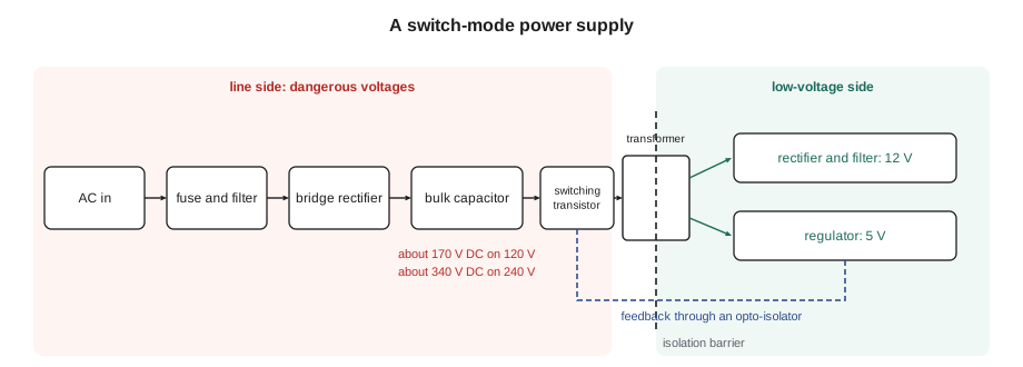
A switch-mode supply first rectifies the incoming AC straight off the line, without a transformer, and charges a large bulk capacitor. The capacitor charges to the peak of the AC wave, not to the voltage a meter shows as the AC value. The peak of a 120 V supply is about 170 V, and of a 240 V supply about 340 V. A small, fast switching transistor then turns this high DC voltage on and off tens of thousands of times a second into a small high-frequency transformer. Because the frequency is so high, the transformer can be tiny. Its output is rectified and filtered again to give the low DC voltages the board needs. A feedback circuit, usually through an opto-isolator, tells the switching chip to adjust so the output stays steady even as the load and the incoming voltage change.
Worked problem
The DC voltage on a bulk capacitor
A switch-mode supply rectifies the household supply directly. What DC voltage will its bulk capacitor reach on a 120 V supply, and on a 240 V supply? The peak of a sine wave is its AC value times √2.
Show solution
- On 120 V:
- \[120 \times \sqrt{2} \approx 120 \times 1.414 \approx 170 \text{ V DC}\]
- On 240 V:
- \[240 \times 1.414 \approx 340 \text{ V DC}\]
Answer: About 170 V DC on a 120 V supply and about 340 V DC on a 240 V supply. That is why an induction cooktop, which runs on 240 V, has a DC bus of about 340 V, as the cooking course showed, and why a capacitor on the line side of any supply must be treated as dangerous.
Capacitors that stay charged
A capacitor stores charge. When the appliance is unplugged, a capacitor on the line side of a supply, on an inverter's DC bus or across a motor, can keep a high voltage for seconds, minutes or longer. Most designs include a bleeder resistor across the capacitor that drains it over time, but bleeders fail, and some circuits drain only through their normal load, which stops when the power goes off. A charged bulk capacitor can give a severe shock and can make a spark that damages a meter probe or the board.
The rule is simple and absolute: after removing power, measure the capacitor's voltage before touching anything near it. Set the meter to DC volts, put the probes across the capacitor's terminals or the test points the tech sheet names, and wait until it reads a safe low value. If the maker's procedure says to discharge the capacitor through a specified resistor, use that resistor with insulated leads, never a screwdriver. Shorting a charged capacitor with a screwdriver can blow pits in the tool, spray molten metal and damage the board's tracks.
Worked problem
How long a bleeder takes
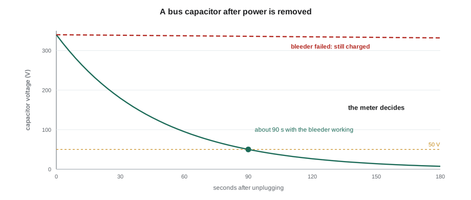
An inverter board has a 470 µF bus capacitor charged to 340 V, with a 100 kΩ bleeder resistor across it. The capacitor's voltage falls with a time constant equal to resistance times capacitance. About how long will it take to fall to 50 V?
Show solution
- Time constant:
- \[\tau = R C = 100{,}000 \times 0.000470 = 47 \text{ s}\]
- Voltage falls as
- \[V = V_0 e^{-t/\tau}\]
- Time to reach 50 V:
- \[t = \tau \ln\frac{V_0}{V} = 47 \times \ln\frac{340}{50} = 47 \times 1.92 \approx 90 \text{ s}\]
Answer: About a minute and a half if the bleeder is working, and much longer, or never, if it has failed. This is why the meter, not the clock, decides when the board is safe.
Worked problem
Energy stored in a bus capacitor
How much energy is stored in the same 470 µF capacitor at 340 V? Energy in a capacitor is half the capacitance times the voltage squared.
Show solution
- \[E = \tfrac{1}{2} C V^2 = 0.5 \times 0.000470 \times 340^2 \approx 27 \text{ J}\]
Answer: About 27 J, delivered in a fraction of a second if it discharges through a hand or a tool. It is enough to cause a painful, dangerous shock and a flash at a screwdriver tip.
Worked problem
Discharging through a resistor
A service manual says to discharge a 470 µF, 340 V capacitor through a 2 kΩ, 5 W resistor on insulated leads. What is the current at the first instant, and what power does the resistor see at that moment? About how long until the voltage is below 5 V?
Show solution
- First current:
- \[I = \frac{340}{2{,}000} = 0.17 \text{ A}\]
- First power:
- \[P = \frac{V^2}{R} = \frac{340^2}{2{,}000} \approx 58 \text{ W}\]
- Time constant:
- \[\tau = 2{,}000 \times 0.000470 = 0.94 \text{ s}\]
- Time to 5 V:
- \[t = 0.94 \times \ln\frac{340}{5} \approx 0.94 \times 4.22 \approx 4 \text{ s}\]
Answer: The resistor sees about 58 W for an instant, far above its 5 W rating, but only for a second or so, which is why the maker specifies a resistor of that size. Hold it on for several seconds, then confirm with the meter that the voltage is near zero.
Isolated and non-isolated supplies
In an isolated supply, the transformer separates the low-voltage outputs from the line. The 5 V and 12 V circuits have no direct connection to the hot or neutral conductor, which makes the low-voltage side much safer to measure and lets the board connect to a touch panel, a Wi-Fi module or a sensor the customer can touch.
Many small, cheaper appliance boards use a non-isolated supply instead. A capacitor-dropper or a small buck converter takes the low voltage straight from the line with no transformer, so the board's "ground" or common is tied to neutral or even to a point that is at line potential. On these boards, every part, including the 5 V circuit, the sensor connectors and the board's common, can be at a dangerous voltage relative to the cabinet and to earth. A meter's common lead clipped to such a board's common is at line voltage. The tech sheet and the board's markings usually show which kind it is; when in doubt, treat the whole board as live.
Two habits follow. Never clip a meter lead to a board's common while the appliance is energized unless the tech sheet says the low-voltage side is isolated and gives that test point. And never connect a grounded instrument such as a bench oscilloscope or a laptop's USB port to a board that may be non-isolated; doing so can short the line through the instrument's ground. Service tools from the maker that connect to a board are designed for it; general-purpose tools are not.
| Feature | Isolated supply | Non-isolated supply |
|---|---|---|
| Transformer | Yes, small high-frequency transformer | No; capacitor dropper or buck converter |
| Low-voltage side referenced to | Its own common, separated from the line | Neutral or a point at line potential |
| Safe to touch low side while live? | Safer, but do not rely on it without the tech sheet | No; treat as fully live |
| Typical use | Main boards, boards with touch panels and Wi-Fi | Small boards, simple controls, some timers |
| Meter common lead | On the named low-voltage test point | Not while energized; follow the tech sheet |
Measuring supply voltages
When a board shows no display or behaves erratically, the supply is one of the first things to check, because nothing else on the board works without it. The tech sheet usually names test points or connector pins for each output. With the meter on DC volts and the common lead on the named low-voltage common, the technician checks each output against the expected value. A 5 V output that reads 4.95 V is fine; one that reads 3.1 V, or that wanders as relays click, is not. Many tech sheets give a tolerance; where they do not, a few hundredths of a volt above or below is normal and a tenth or more off is suspicious (typical).
A low supply voltage does not always mean the supply has failed. A short circuit somewhere on the low-voltage side, such as a sensor with water in its connector, a crushed harness to the user interface or a failed display board, can pull the supply down. The supply is working, but it cannot hold its voltage against the short. To tell the difference, disconnect the external loads on that supply one at a time, such as the user interface harness, then measure again. If the voltage comes back when one harness is unplugged, the fault is on that harness or the board it feeds.
Worked problem
A regulator that runs hot
A board's 5 V linear regulator takes 12 V in and supplies 0.2 A to the microcontroller and display. How much power does it turn into heat?
Show solution
- \[P = (V_{in} - V_{out}) \times I = (12 - 5) \times 0.2 = 1.4 \text{ W}\]
Answer: About 1.4 W, enough to make the regulator too hot to touch comfortably. That is normal for this kind of regulator, and it is why such regulators sit on a small heat sink. A regulator much hotter than normal, with a 5 V output that sags, points to too much current drawn from the 5 V side.
Fuses and protective parts
Boards protect themselves with small fuses, fusible resistors that open like a fuse when overloaded, and varistors (metal-oxide varistors, MOVs) that clamp voltage spikes from the line. A varistor that has absorbed a large surge may crack, scorch or blow, often taking the fuse with it. An open fuse on a board is a symptom: something drew too much current. On most appliance boards the fuse is soldered in and not intended to be replaced in the field, and even where it is replaceable, replacing it without finding the cause usually ends with a second open fuse and sometimes a damaged board.
Hiro's induction board showed the pattern well. The open fuse and the cracked filter capacitor near a scorch told him the board had failed internally, probably after a surge. He checked that the cooktop's coils and fan were not shorted before ordering the new power board, because a shorted coil could have caused the same damage. He also asked the customer about recent storms and power cuts, noted the answer on the work order, and suggested the customer ask an electrician about whole-house surge protection, which is the electrician's work, not Penfold's.
Ines closed the session with a rule she wrote on the whiteboard in large letters: "Unplug. Wait. Measure. Then touch." Kiran copied it under the line from the first hour.
Common mistakes
MistakeAssuming a board is safe because the appliance is unplugged.
InsteadMeasure the bus and bulk capacitors with the meter before touching; bleeders fail.
MistakeDischarging a capacitor with a screwdriver.
InsteadUse the maker's specified resistor on insulated leads, then confirm with the meter.
MistakeClipping the meter's common to a non-isolated board while it is live.
InsteadTreat the whole board as live and use only the test points the tech sheet names.
MistakeCondemning the supply when its voltage is low.
InsteadUnplug external loads one at a time; a short elsewhere can pull a good supply down.
MistakeReplacing a board fuse without finding why it opened.
InsteadFind the shorted load or surge damage first; on most boards the fuse is not a field part.
Summary and key terms
- Boards need low DC voltages such as 5 V, 3.3 V, 12 V and 15 V, and motor drives need a high DC bus.
- Switch-mode supplies rectify the line, charge a bulk capacitor to the peak voltage and switch it at high frequency.
- A bulk capacitor reaches about 170 V DC on 120 V and about 340 V DC on 240 V.
- Capacitors can stay charged after power is removed; always measure before touching.
- Discharge only with the maker's resistor on insulated leads.
- Non-isolated supplies put the board's low-voltage side at line potential.
- A low supply voltage can be caused by a short on a load; unplug loads one at a time.
- Open fuses and blown varistors are symptoms of overloads or surges.
- Switch-mode power supply
- A supply that switches rectified line voltage at high frequency through a small transformer.
- Bulk capacitor
- The large capacitor that stores the rectified line voltage in a supply.
- DC bus
- The high DC voltage inside an inverter or induction board.
- Bleeder resistor
- A resistor that drains a capacitor after power is removed.
- Isolated supply
- A supply whose low-voltage side is separated from the line by a transformer.
- Non-isolated supply
- A supply whose low-voltage side is connected to the line.
- Opto-isolator
- A part that passes a signal by light across an isolation barrier.
- Varistor
- A part that clamps voltage spikes from the supply.
Practice problems
Work each problem on paper first, then reveal the answer to check.
What DC voltage does a bulk capacitor reach on a 240 V supply?
Show answer
About 340 V.
What must be done before touching a board's capacitor after unplugging?
Show answer
Measure its voltage and wait until it is near zero.
Why is a non-isolated board dangerous to probe while live?
Show answer
Its low-voltage circuits are at line potential.
A 5 V output reads 3 V. What should be checked before condemning the supply?
Show answer
Whether a load such as a harness or sensor is shorting it.
What does an open board fuse usually mean?
Show answer
Something drew too much current or a surge damaged the board.
Lesson quiz · 5 questions
Score 60% or more to complete this lesson.
Create a free account to save your progress, take quizzes and earn a certificate.