
APP-320 · Lesson 4 of 12 · 27 min
Thermistors, pressure and position sensors
▶ Video coming soon A video version of this lesson is on the way.
On Wednesday, August 19, Dee had a call from Ottoline Tamberlane in Kentley. Her six-year-old bottom-freezer refrigerator was freezing the lettuce in the fresh food section, and the display, set to 3 °C (37 °F), kept showing that temperature as if all were well. A thermometer in a glass of water on the middle shelf read 0 °C (32 °F). Dee entered the service mode, which showed the fresh food sensor reading as 25 °C (78 °F), warmer than the kitchen. With the refrigerator unplugged, she found the thermistor behind the air duct cover, clipped into the airflow, with its two-wire connector sitting in a small puddle from a blocked duct drain. The thermistor itself read about 9,800 Ω instead of the 28,700 Ω the sample table gave for 3 °C (37 °F). The board had believed the compartment was warm and kept cooling. A new thermistor with a sealed splice, and a cleared duct drain, brought the reading back in line.
This lesson explains the sensors that tell an appliance's control what is happening: thermistors and other temperature sensors, pressure and level sensors, flow meters, Hall-effect and reed switches for position and speed, turbidity sensors, and door switches. For each, it covers how the sensor works, what the board expects to see, how it usually fails, and how to test it.
Why sensors matter
A control can only be as good as the information it gets. A refrigerator runs its compressor, fans and defrost heater according to what its thermistors report. A washer fills, heats and spins according to its pressure sensor, thermistor and motor speed sensor. A dishwasher heats until its thermistor reports the target and drains until its turbidity sensor sees clean water. When a sensor drifts, fails or loses its connection, the board does exactly what the wrong information tells it to, and the customer sees a fault that looks like a failed compressor, heater or board. That is why Dee checks sensors early, and why the service mode's sensor readout is one of the most useful screens on the machine.
Thermistors
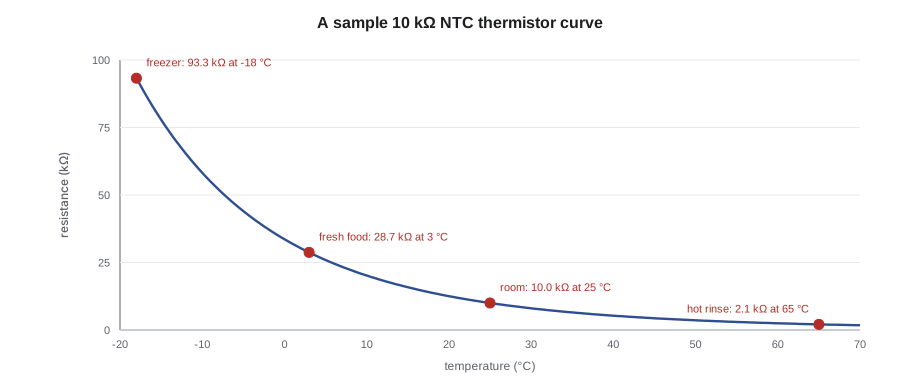
A thermistor is a resistor whose resistance changes with temperature. Most appliance thermistors are NTC (negative temperature coefficient) types: as they get warmer, their resistance falls. A common type has a resistance of 10,000 Ω at 25 °C (77 °F), rising to tens of thousands of ohms in a freezer and falling to a few thousand ohms in hot wash water (typical; the exact values depend on the part). Makers use many different curves, so the tech sheet gives a table for each sensor. The curve below and the table that follows use one common sample curve, a 10 kΩ part with a constant called β of 3950, as Penfold's binder does.
| Temperature | Resistance (sample curve) | Where it is typical |
|---|---|---|
| −18 °C (0 °F) | about 93,300 Ω | Freezer |
| 0 °C (32 °F) | about 33,600 Ω | Ice and water |
| 3 °C (37 °F) | about 28,700 Ω | Fresh food compartment |
| 10 °C (50 °F) | about 20,200 Ω | Cool water |
| 25 °C (77 °F) | 10,000 Ω | Room temperature |
| 40 °C (104 °F) | about 5,300 Ω | Warm wash water |
| 65 °C (149 °F) | about 2,100 Ω | Hot rinse water |
Worked problem
Reading a thermistor against its table
A fresh food thermistor, unplugged and measured at its connector, reads 9,800 Ω. A thermometer beside it reads 3 °C (37 °F). Using the sample table, what temperature does the board think it is, and what will it do?
Show solution
- At 3 °C (37 °F) the thermistor should read about 28,700 Ω.
- 9,800 Ω is slightly below the 10,000 Ω value for 25 °C (77 °F), so the board reads about 25 °C (78 °F).
- The board believes the compartment is far too warm and keeps cooling.
Answer: The board sees about 25 °C (78 °F) and runs the compartment colder than it should. A low reading on an NTC thermistor makes the board think it is warm; a high reading makes it think it is cold. Water in the connector is a common cause of a low reading.
Thermistors are tested in three ways. In the service mode, many controls show each sensor's temperature; a reading that disagrees with a thermometer beside the sensor by more than a few degrees, or one that shows an impossible value such as −40 °C (−40 °F) or 150 °C (302 °F), is a strong clue. With an ohmmeter, the thermistor is unplugged and its resistance compared with the table at the measured temperature; hold the probes on the connector, not the sensor body, and avoid warming the sensor with your hand. With a voltmeter, the voltage at the board's sensor input is measured with everything connected, and compared with the value the tech sheet gives.
The voltage test works because the board reads a thermistor through a voltage divider: the board's 5 V (or 3.3 V) supply feeds a fixed resistor in series with the thermistor, and the microcontroller measures the voltage across the thermistor. As the thermistor's resistance changes, so does that voltage.
Worked problem
The voltage the board sees
A board feeds its thermistor from 5 V through a 10,000 Ω fixed resistor, and measures the voltage across the thermistor. What voltage does it see at 3 °C (37 °F) (28,700 Ω), at 25 °C (77 °F) (10,000 Ω), with the sensor unplugged, and with the sensor wires shorted together?
Show solution
- At 3 °C (37 °F):
- \[V = 5 \times \frac{28{,}700}{28{,}700 + 10{,}000} \approx 3.71 \text{ V}\]
- At 25 °C (77 °F):
- \[V = 5 \times \frac{10{,}000}{20{,}000} = 2.50 \text{ V}\]
- Unplugged: the thermistor is an open circuit, so the input rises to the full 5 V.
- Shorted: the thermistor is zero ohms, so the input falls to 0 V.
Answer: About 3.71 V cold, 2.50 V at room temperature, 5 V open and 0 V shorted. A board that sees 5 V or 0 V usually reports a sensor fault code, because no real temperature gives those voltages. (This divider arrangement is one common design; the tech sheet gives the actual circuit and values.)
Some appliances use other temperature sensors. Ovens commonly use a platinum RTD, about 1,000 Ω at 0 °C (32 °F) and rising as it heats, as the cooking course explained. A few use thermocouples. The method is the same: compare the reading with the maker's table at a known temperature, check the connector and harness, and check what the board reports.
Pressure and level sensors
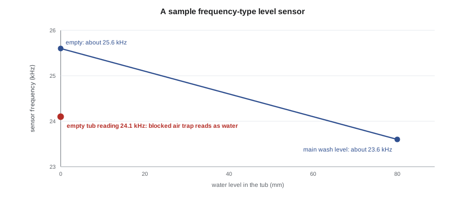
Washers and dishwashers need to know how much water they hold. Older machines used a pressure switch: a diaphragm connected by a hose to an air trap low in the tub, which closed contacts at one or two fixed levels. Many modern machines use an analog pressure sensor, which reports the level continuously. A common design is a small sensor whose output is a frequency: as the water rises, air pressure in the hose rises, a diaphragm moves a core inside a coil, and the frequency of an oscillator changes. The board converts that frequency into a water level. The laundry course showed one: a front-loader's sensor reading about 25.6 kHz empty, with sludge in the hose making it read 24.9 kHz, as if water were still there.
Other designs output a voltage, typically between about 0.5 V and 4.5 V across their range (typical), and some pressure sensors are built into the board itself with only the hose connecting to them. The tech sheet gives the expected values at empty and at a known level. The most common faults are not in the sensor at all: a kinked, split or loose hose, a clogged air trap or air dome, or sludge in the hose, all of which make the reading wrong. Blowing gently into a disconnected hose, never sucking, and watching the reading in the service mode is a quick check on some models, if the maker's instructions allow it.
Worked problem
Reading a frequency-type level sensor
A washer's service mode shows the level sensor frequency. The tech sheet gives about 25.6 kHz empty and about 23.6 kHz at the main wash level for this sample sensor, with the frequency falling as the level rises. With the tub drained, the reading is 24.1 kHz. What does this suggest?
Show solution
- Empty should read about 25.6 kHz.
- 24.1 kHz is well below that, close to the reading for a partly filled tub.
- The board thinks there is still water in the tub.
Answer: The sensor is reporting water that is not there. Check the hose and air trap for water, sludge or a kink before suspecting the sensor; a blocked air trap holds pressure and gives exactly this reading.
Flow meters measure the water entering a machine instead of its level. A small turbine in the inlet path spins as water flows, and a magnet on the turbine passes a Hall-effect sensor, which sends a pulse for each turn. The board counts pulses: the laundry course used a sample meter giving about 400 pulses per litre. A flow meter that sends no pulses makes the board think no water is arriving, usually ending in a long-fill code even though the tub is filling.
Hall-effect sensors and reed switches
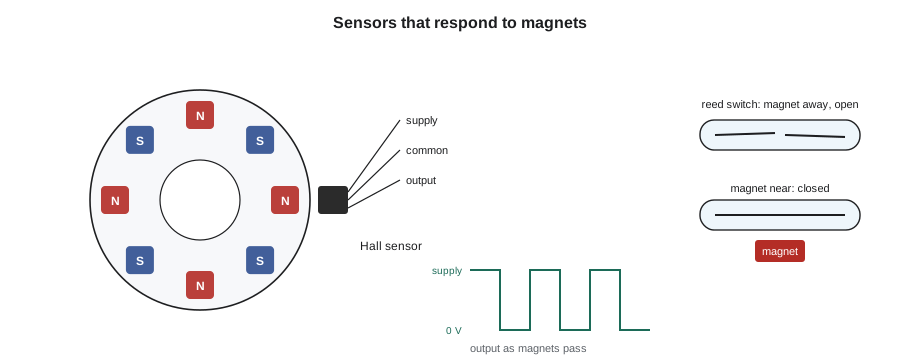
A Hall-effect sensor is a small semiconductor that switches or changes its output when a magnetic field passes it. Appliances use Hall sensors to measure motor speed (a magnet ring on the rotor passes the sensor), to sense position (a magnet on a lid, a door, a wash arm or an ice maker's arm), and to count flow-meter pulses. A typical Hall sensor has three wires: a supply, often 5 V or 12 V, a common, and an output that switches between near 0 V and near the supply voltage as magnets pass (typical). With the sensor connected and powered, turning the drum or wheel slowly by hand should make the output toggle; a meter on DC volts shows it switching.
Worked problem
Counting speed sensor pulses
A motor's speed sensor gives 12 pulses for each turn of the rotor. At a spin speed of 1,200 revolutions per minute, how many pulses per second does the board receive?
Show solution
- Turns per second:
- \[1{,}200 \div 60 = 20 \text{ turns per second}\]
- Pulses per second:
- \[20 \times 12 = 240 \text{ Hz}\]
Answer: The board receives about 240 pulses a second and uses them to hold the speed it commands. If the sensor stops pulsing, the board cannot tell how fast the motor turns and stops with a speed fault, such as the sample Northwind code F51.
A reed switch is a pair of thin metal contacts sealed in a small glass tube. A nearby magnet pulls them together. Reed switches are used for door sensing on some refrigerators, for float switches and for lid position. They are tested with an ohmmeter while moving a magnet toward and away from them: closed, they read near zero; open, they read very high. Because they are made of glass, they crack if a panel is forced or a cabinet is twisted.
Turbidity, door and other sensors
A dishwasher's turbidity sensor shines infrared light across the water to a receiver; dirty water scatters and blocks more light. The board uses it to decide how long to wash and whether an extra rinse is needed. Films of detergent, hard-water scale and a soiled lens give false readings, so the first step is cleaning the sensor as the maker describes. Some turbidity sensors include a thermistor in the same housing.
Door switches tell the control a door is shut or open. They may be simple switches, switch assemblies with several sets of contacts, or part of a door lock that also confirms locking. A board that believes a door is open will not run, and a board that believes it is shut when it is not may leave a light off or a fan running. Door switches are tested with an ohmmeter in both positions, and in the service mode, which often shows the switch state directly.
Some appliances add more: humidity sensors in a few dryers and ovens, moisture sensor bars in dryers (the laundry course), oxygen or steam sensors in combination ovens, leak detection pads or floats under dishwashers, and load sensing that uses the motor's own current rather than a separate sensor. The same three questions apply to each: what does the board expect, what is it actually seeing, and is the problem the sensor, its connection or its environment?
Dee's refrigerator call ended with a lesson about environment. The thermistor had failed because water from a blocked duct drain had soaked its connector. A new thermistor alone would have failed again within months. Clearing the drain, adding a sealed splice and checking that the duct cover was seated properly fixed the cause.
Common mistakes
MistakeReading a thermistor with the hand wrapped around it.
InsteadHold the probes on the connector and let the sensor sit at the temperature being measured.
MistakeCondemning a thermistor without knowing the actual temperature.
InsteadMeasure the temperature beside it with a thermometer and compare with the tech sheet table.
MistakeReplacing a level sensor that reads water in an empty tub.
InsteadCheck the hose and air trap for water, sludge and kinks first.
MistakeTesting a Hall sensor unpowered with an ohmmeter.
InsteadTest it powered and connected, watching the output toggle as the magnet passes.
MistakeReplacing a wet sensor without finding where the water came from.
InsteadFix the leak, drain or condensation that soaked it.
Summary and key terms
- Boards act on what their sensors report; wrong sensor readings mimic failed parts.
- NTC thermistors fall in resistance as they warm; a low reading looks warm and a high one looks cold.
- Thermistors are tested in service mode, with an ohmmeter against the table, or by the voltage at the board's input.
- Open thermistors give full supply voltage at the input and shorted ones give 0 V, usually with a sensor code.
- Analog level sensors report pressure as a frequency or a voltage; hoses and air traps cause most faults.
- Flow meters and speed sensors send pulses from a magnet passing a Hall sensor.
- Reed switches close with a magnet and are tested with an ohmmeter while moving one.
- Turbidity and door sensors are cleaned and checked before being replaced.
- Thermistor
- A resistor whose resistance changes with temperature.
- NTC
- Negative temperature coefficient: resistance falls as temperature rises.
- Voltage divider
- Two resistances in series that split a voltage in proportion.
- Analog pressure sensor
- A sensor that reports water level continuously.
- Flow meter
- A sensor that counts water flow as pulses.
- Hall-effect sensor
- A semiconductor sensor that responds to a magnetic field.
- Reed switch
- A sealed glass switch closed by a magnet.
- Turbidity sensor
- A light sensor that measures how dirty the water is.
Practice problems
Work each problem on paper first, then reveal the answer to check.
An NTC thermistor reads lower than its table value. What does the board think?
Show answer
That it is warmer than it really is.
What voltage does a board input see with its thermistor unplugged in a typical divider?
Show answer
The full supply voltage, such as 5 V.
A washer's level sensor shows water in an empty tub. What should be checked first?
Show answer
The pressure hose and air trap.
How is a Hall-effect speed sensor tested?
Show answer
Powered and connected, turning the rotor slowly and watching the output toggle.
What should be done before replacing a turbidity sensor?
Show answer
Clean it as the maker describes and retest.
Lesson quiz · 5 questions
Score 60% or more to complete this lesson.
Create a free account to save your progress, take quizzes and earn a certificate.