
APP-320 · Lesson 1 of 12 · 26 min
Electronics in modern appliances
▶ Video coming soon A video version of this lesson is on the way.
On Saturday, October 24, the sixth day of Kiran's apprenticeship, Penfold's shop was set up like a classroom. Ines Quillfeather, a field service trainer for one of the three brands Penfold is authorized to service, had driven in with a crate of control boards, sensors and a cut-away washer. Dee and Hiro sat at the back. Ines started by holding up two parts: a 1990s washer timer, a plastic box with a motor, a cam stack and a dozen brass contacts, and a modern washer control board no bigger than a paperback. "These do the same job," she said. "The timer does it with cams. The board does it with a program, a handful of sensors and a lot of very small parts that do not like being guessed at. By the end of today I want you to treat the board as the last thing you suspect, not the first."
This lesson explains why electronic controls replaced electromechanical timers, what the main parts of an appliance control system are, how inputs and outputs connect to a control board, what the board can and cannot tell the technician, and the habits that make electronic diagnosis accurate. Later lessons in this course take each part in turn: power supplies (lesson 2), boards and user interfaces (lesson 3), sensors (lesson 4), inverter compressors and motors (lessons 5 and 6), communication (lesson 7), service modes and fault codes (lessons 8 and 9), connected appliances (lesson 10) and board handling (lesson 11). Lesson 12 brings them together on a day of service calls.
From cams to code
Older washers, dryers and dishwashers were controlled by a mechanical timer. A small synchronous motor turned a stack of plastic cams at a fixed speed, and each cam opened or closed a set of contacts. One cam turned the fill valve on for two minutes, another started the agitate motor, another switched the drain pump. The program was carved into the cams. If the customer wanted a different cycle, the dial simply started the cams at a different place. A timer could be tested with an ohmmeter and its chart, contact by contact, and a technician could follow its logic with a pencil on the wiring diagram.
Modern appliances use an electronic control: a printed circuit board with a microcontroller, a small computer on one chip that runs a fixed program stored in its memory. The microcontroller reads inputs such as a door switch, a water level sensor and a thermistor, makes decisions in its program, and switches outputs such as valves, pumps, heaters and motors through relays, triacs or motor drives. Because the program can measure as well as switch, it can do things a timer never could: fill by the actual water level instead of by time, weigh a load by how hard the motor works to turn it, end a dry cycle when the clothes are dry, adjust a refrigerator's defrost to how often the door is opened, and run a compressor at exactly the speed the load needs.
Makers moved to electronic controls for several reasons. Energy and water standards in both countries pushed appliances to use less, and sensors and variable-speed motors are the cheapest way to do that. Electronics cost less to make than a timer with dozens of moving contacts, take less space and allow one board to run many models by changing a setting. They also let the appliance protect itself: a board can stop a heater that runs too long, shut off a valve when a leak sensor trips, and record what went wrong. For the customer, the result is quieter machines with more cycles. For the technician, it means fewer worn contacts and more diagnosis by measurement and by reading what the control reports.
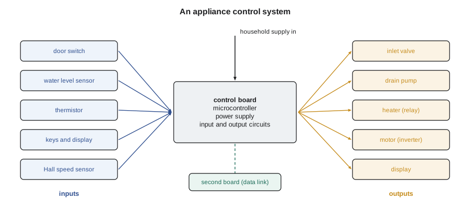
The parts of an electronic control system
Almost every electronic appliance has the same building blocks, even when they are arranged differently from one brand to another.
- Power supply. The board needs low, steady DC voltages, typically 5 V or 3.3 V for the microcontroller and 12 V or 15 V for relay coils and sensors (typical). A power supply on the board, or a separate supply board, makes them from the household supply. Lesson 2 covers how.
- Microcontroller. The chip that runs the program. It is not repaired or replaced on its own in the field; if it fails, the whole board is replaced.
- Input circuits. Resistors, filters and small parts that turn a switch closing or a sensor's resistance into a voltage the microcontroller can read.
- Output drivers. Relays for heaters and larger motors, triacs for valves and small pumps, and transistor drivers for DC loads and for signals to other boards.
- User interface. The keys, knobs, touch pads and display, sometimes on the main board and often on a separate user interface board connected by a harness.
- Motor drives. In machines with variable-speed motors, an inverter or motor control board that turns DC into the variable-frequency power the motor needs (lessons 5 and 6).
- Memory and communication. Stored settings, the model's configuration, a list of past faults, and in many machines a data link between boards and, in connected models, a Wi-Fi module (lessons 7 and 10).
| Function | Mechanical timer appliance | Electronic control appliance |
|---|---|---|
| Program | Cams on a motor-driven shaft | Program in the microcontroller |
| Water fill | By time, or by a pressure switch | By a pressure sensor or flow meter, measured continuously |
| Motor speed | One or two fixed speeds | Any speed, set by the program through an inverter |
| Fault handling | None; the timer keeps turning | Stops the cycle, shows a code, records the fault |
| Testing | Contact chart and ohmmeter | Service mode, fault history and measurements at the loads and sensors |
| Typical repair | Replace timer or switch | Repair the root cause, then replace the board only if proven |
Inputs, outputs and the decisions in between
It helps to think of the board as a manager that knows only what its inputs tell it and can act only through its outputs. If a washer's door lock switch reports the door is open, the board will not start the cycle, even if the door is plainly locked; the board is not wrong, it is believing a bad input. If the board tells the drain pump to run and the pump is open-circuited, the water stays, the board waits, and after a set time it stops and reports a drain fault. Most electronic faults are found by asking two questions: is the board getting the right information, and is the board's command reaching a part that works?
That gives a simple method that Dee repeats on every electronic call. First, confirm the complaint and read any fault code or fault history. Second, check the inputs the program depends on: sensors, switches and the signals between boards. Third, command the outputs in the service mode or test mode and measure at the load whether the voltage arrives. A part that receives its correct voltage and does nothing has failed. A part that never receives its voltage points back up the line: to the harness, the connector, the safety switches in series with it, and only then to the board's output.
Worked problem
Following one output from board to load
A dishwasher shows a no-fill code. In test mode, the inlet valve is commanded on. At the valve's terminals the technician reads 0 V AC. At the board's valve connector, with the harness plugged in, the reading is 120 V AC. What does this tell the technician, and what comes next?
Show solution
- The board is sending power: 120 V is present at its output connector.
- The power is not arriving at the valve: 0 V at the valve terminals.
- Somewhere between them, the path is broken: the harness, a connector, or a switch wired in series with the valve such as the flood switch on many models.
- Next step: with the power off, check continuity of each wire from the board connector to the valve, and check the flood switch position.
Answer: The fault is between the board and the valve, not in the board. Replacing the board would not fix it.
What a board can and cannot tell you
A modern control board is a useful diagnostic partner. It can show a fault code when something is out of range, store a fault history with the most recent faults, run each output in a component test so the technician can check it, display sensor readings such as temperatures and water levels, and report its software version. Lessons 8 and 9 explain how to get into these modes and use what they show.
A board can be misleading, though. A fault code tells the technician what the board noticed, not what broke. A long-drain code means the water level did not fall in time; the cause might be a sock in the pump, a kinked hose, a failed pump, a broken wire or, rarely, the board's own output. A thermistor code means the board saw a resistance it did not expect; the cause might be the thermistor, its connector, a wire pinched in a door hinge, or water in a connector. Every code is a starting point for measurements, never the answer by itself.
Boards also reflect their environment. A board that has been wet, overheated or exposed to a power surge may fail, but so may the part that caused the water, heat or surge. A burned relay on a board often means the load it switched was shorted or drawing too much current. Replacing the board without finding the shorted heater or the seized motor will burn the new board too. This is why Penfold's rule, which Ines repeated in her own words, is to find the root cause before ordering a board.
Worked problem
Why a cheap measurement beats a guessed board
A technician suspects a washer's main board. The board costs about 340 dollars and cannot be returned once installed, as is common for electrical parts. Fifteen minutes of measurement at Penfold's labour rate of 110 dollars an hour would confirm or rule it out. Compare the cost of measuring with the cost of a wrong guess.
Show solution
- Cost of measuring:
- \[0.25 \text{ h} \times 110 = 27.50 \text{ dollars}\]
- Cost of a wrong board: about 340 dollars, plus a second visit to find the real fault.
- Ratio:
- \[340 \div 27.50 \approx 12\]
Answer: A wrong board costs about 12 times the measurement that would have prevented it, before counting the second trip and the customer's confidence.
Low-power electronics next to high-power loads
One feature makes appliance electronics different from a computer on a desk: the board sits beside heaters, motors and water. Parts on the same board may switch 120 V or 240 V at several amps while the microcontroller runs on a few volts. The board is designed to keep these apart, with spacing between tracks, opto-isolators or relays between the high and low sides, and fuses or fusible resistors. The technician must respect the same separation: line voltage can be present on parts of a board that look like small electronics, and on some boards the low-voltage side is not isolated from the line at all (lesson 2).
Heat and moisture are the enemies of boards. Boards are often coated with a thin conformal coating or potted in resin, mounted high in the cabinet and placed where air can reach them. When a technician sees a board mounted in a new place, a missing cover, a blocked vent or water tracks on the cabinet, those are clues to why the board failed and to what must be fixed so the next one survives.
Worked problem
Standby power of an electronic control
A washer's control board draws about 0.5 W in standby, 24 hours a day, every day (a typical figure for a modern appliance). How much energy is that in a year?
Show solution
- Hours in a year:
- \[24 \times 365 = 8{,}760 \text{ h}\]
- Energy:
- \[0.5 \text{ W} \times 8{,}760 \text{ h} = 4{,}380 \text{ Wh} = 4.38 \text{ kWh}\]
Answer: About 4.4 kWh a year. Standby power is small, but it explains why boards are always partly live while the appliance is plugged in, and why the technician must unplug or switch off at the panel before working on them.
Reading the board's documents
Every appliance with electronic controls comes with a tech sheet, usually folded inside the cabinet, behind the kick plate or in a pocket on the back. It gives the wiring diagram, connector pin numbers, expected voltages and resistances, the service mode steps and the fault code list for that model. The maker's service portal often has a longer service manual and service bulletins. These documents belong to the maker and are written for one model; the technician reads them for each machine rather than trusting memory, because the same code can mean different things in different brands and even in different years of one brand.
Kiran's training binder at Penfold uses an invented brand, Northwind, for practice. Its sample fault codes, such as F21 for a long drain and F60 for lost communication between boards, appear throughout this course. They are examples only. In the field, always use the tech sheet of the machine in front of you.
Ines ended the first hour by passing the timer and the board around the room. "With the timer," she said, "you tested the part. With the board, you test what goes in and what comes out. The board is usually the messenger." Kiran wrote that line on the inside cover of his notebook.
Common mistakes
MistakeReplacing the board because the fault code mentions it.
InsteadTreat the code as a pointer: check the inputs and the load first, and replace the board only when measurement proves its output or power supply has failed.
MistakeTrusting memory for a code meaning or a connector pin.
InsteadRead the tech sheet for that model every time; codes and pins change between brands and years.
MistakeInstalling a new board without finding why the old one burned.
InsteadLook for a shorted load, water, overheating or a pinched harness, and fix it first.
MistakeTreating the low-voltage parts of a board as safe to touch while plugged in.
InsteadUnplug or switch off at the panel; parts of many boards are at line voltage or connected to it.
MistakeExpecting a board to fail often.
InsteadMost electronic faults are sensors, switches, connectors, harnesses and loads; boards are the minority.
Summary and key terms
- Electronic controls replaced mechanical timers with a microcontroller that reads inputs and switches outputs.
- Sensors and variable-speed drives let appliances save energy and water and protect themselves.
- Every control system has a power supply, a microcontroller, input circuits, output drivers, a user interface and often motor drives and communication.
- Diagnose by asking whether the board gets the right information and whether its commands reach a working part.
- A fault code reports what the board noticed, not what broke.
- Burned board parts usually point to a shorted or overloaded load that must be fixed first.
- Boards share space with line voltage, heat and water; respect the separation and look for environmental causes.
- Use the tech sheet and service manual for each model; Northwind codes in this course are samples.
- Microcontroller
- A small computer on one chip that runs the appliance's control program.
- Input
- A signal the control reads, such as a switch position or a sensor's resistance.
- Output
- A load or signal the control switches, such as a valve, pump, heater or motor.
- Tech sheet
- The model-specific service sheet with the wiring diagram, values and fault codes.
- Fault history
- The list of recent faults stored in a control's memory.
- Component test
- A service mode that switches each output on so the technician can check it.
- Mechanical timer
- A motor-driven cam switch that controlled older appliances.
Practice problems
Work each problem on paper first, then reveal the answer to check.
What does a microcontroller do in an appliance?
Show answer
It runs the control program: it reads inputs and switches outputs.
A valve gets its correct voltage but does not open. What has failed?
Show answer
The valve.
A valve gets no voltage, but the board's connector has voltage. Where is the fault?
Show answer
In the harness, a connector or a series switch between them.
Why is a fault code not a diagnosis?
Show answer
It tells what the board noticed, not what caused it.
Why must the cause of a burned relay be found before a new board is installed?
Show answer
A shorted or overloaded load will burn the new board too.
Lesson quiz · 5 questions
Score 60% or more to complete this lesson.
Create a free account to save your progress, take quizzes and earn a certificate.