
APP-320 · Lesson 3 of 12 · 26 min
Control boards and user interfaces
▶ Video coming soon A video version of this lesson is on the way.
Dee's case file for Friday, September 4, before Kiran started, was the one Ines asked her to tell. Rasmus Ekdahl in Greensville had a four-year-old dishwasher whose touch panel would not respond: the display lit, but pressing Start did nothing, and pressing Normal sometimes selected Heavy instead. The customer had already watched a video and ordered a new main board online. Dee asked him to keep it in its bag. She ran the dishwasher's keypad test from the service mode, which lit a segment for each key the board saw. Two keys did not register, and a third registered as its neighbour. She lifted the door's top panel and found the keypad's ribbon cable creased where it folded over the door's edge, with a faint brown tide line of dried rinse aid along the fold. A new user interface assembly, with its own ribbon cable, fixed it. The new main board went back to the online seller unopened.
This lesson describes what is on an appliance control board, how relays and triacs switch the loads, how user interfaces such as membrane keypads, capacitive touch panels, encoders and displays connect to the board, and where the line falls between parts the technician replaces and parts that are not repaired in the field.
What is on a main board
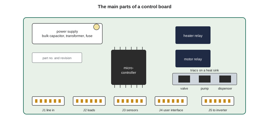
Open the cover of a typical washer, dishwasher or refrigerator main board and the same families of parts appear. Large black relays with their coil and contact ratings printed on top. Small three-legged triacs, often on a heat sink. One or more connectors along the edges, each keyed so it fits only one way. Rows of small surface-mount resistors and capacitors. The microcontroller, a square chip with many pins. The power supply section from lesson 2, with its bulk capacitor and small transformer. Often a few test points, a fuse, and a printed part number and revision. Some boards are covered by a plastic tray or potted in resin to keep out moisture, and many are coated with a clear lacquer.
The technician does not repair these parts. Field service works at the level of the whole board, the harnesses and connectors that join it to the appliance, and the loads and sensors it controls. A failed relay, triac or chip means a replacement board. The work lies in proving that the board, and not something it is connected to, is at fault.
Relays and triacs
A relay is a switch worked by a small electromagnet. The board's driver puts 12 V DC across the relay's coil, the coil pulls in an armature, and the armature closes contacts that carry the load's current, such as a 1,100 W dishwasher heater or a dryer's motor. The coil circuit and the contact circuit are separate, so a relay lets a few milliamps of low-voltage current switch several amps at 120 V or 240 V. Relays click when they operate, which is a useful sign in a component test: a click with no voltage at the load points to burned contacts or a broken track after the relay.
Worked problem
Relay coil current and contact load
A board relay has a 12 V DC coil of 400 Ω and contacts rated 16 A at 250 V AC. It switches a dishwasher heater of 1,100 W at 120 V. What current does the coil draw, and is the contact rating enough?
Show solution
- Coil current:
- \[I = \frac{12}{400} = 0.030 \text{ A} = 30 \text{ mA}\]
- Heater current:
- \[I = \frac{1{,}100}{120} \approx 9.2 \text{ A}\]
- Compare with the contact rating: 9.2 A is less than 16 A.
Answer: The coil draws about 30 mA, and the contacts carry about 9.2 A, within their 16 A rating. If the heater were shorted, the current could far exceed the rating and weld or burn the contacts, which is why a burned relay sends the technician to check the load.
A triac is a solid-state switch for AC. It has no moving parts and no click, and it is used for smaller loads that switch often, such as inlet valves, drain pumps, dispensers and door lock solenoids. A triac that fails usually fails shorted, leaving its load on all the time, or open, so the load never receives voltage. A shorted inlet valve triac is a classic cause of a dishwasher or washer that keeps filling with the power on and the door open; on most models the flood switch then runs the drain pump and stops the cycle with a code.
Measuring a triac-switched output needs care. Many triac outputs have a small snubber circuit across them that lets a tiny current leak through even when the triac is off. A digital meter with a very high input resistance connected to an open load or a disconnected connector may then read most of the line voltage, a ghost voltage, even though the triac is off. Measuring with the load connected, or using a meter with a low-impedance (LoZ) setting, avoids being fooled. The same caution applies to long harness runs, where voltage can couple from one wire to its neighbour.
User interfaces
The user interface is the part the customer touches: keys, knobs, displays and lights. It may be built into the main board, but on most modern appliances it is a separate user interface board behind the control panel, connected to the main board by a ribbon cable or a harness. Lesson 7 explains how they talk to each other.
- Membrane keypads are layers of thin plastic with printed conductive tracks. Pressing a key pushes one layer's contact onto another and closes a circuit. They are sealed against spills but crack along folds, and their tails, flat ribbons with printed conductors, are fragile. A key can be tested with an ohmmeter on the tail's contacts: closed, it reads low, often under about 100 Ω (typical); open, it reads very high. The tech sheet gives the pin pairs for each key.
- Tactile switches are small push-button switches soldered to a board behind plastic buttons. They wear out with use, and the keypad test in service mode shows which ones register.
- Capacitive touch panels sense the change in capacitance when a finger comes near a pad behind glass or plastic. They have no contacts to wear, but they are upset by water, grease films, a damp cloth left on the panel, cracked glass and poor grounding. Many lock out briefly if they sense water, which customers report as "the panel stopped working when I wiped it."
- Rotary encoders are knobs that turn without stops and send pulses as they turn; the board counts the pulses to move through cycles. A worn encoder skips or jumps settings.
- Displays may be LED segments, a backlit LCD or, on premium models, a small touch screen. A display that is dim or missing segments, while the keys work, points to the display or its board rather than the main board.
| Interface | Typical failure | Quick check |
|---|---|---|
| Membrane keypad | Cracked tail at a fold, liquid ingress | Keypad test in service mode; ohmmeter on the tail's key pins |
| Tactile switch | Worn switch, no click or no registration | Keypad test; feel for the click |
| Capacitive touch | Water lockout, cracked glass, grounding | Dry and clean the panel; keypad test; check the panel's ground |
| Rotary encoder | Skipping or jumping settings | Watch the display while turning slowly |
| Display | Dim, missing segments | Display test in service mode |
Dee's dishwasher showed why the keypad test matters. The symptom, keys not working, sounded like a board. The test showed two keys missing and one crossed, a pattern that fits a damaged ribbon far better than a failed microcontroller. The tide line of rinse aid explained it: the dishwasher had been overfilled with rinse aid for months, and it had crept along the door into the fold of the cable.
Boards, revisions and configuration
Boards are identified by a part number, often with a revision letter or number. Makers revise boards to fix problems, change suppliers or merge several old boards into one new one. A service bulletin may say that a newer board replaces an older one, sometimes with an adapter harness or an instruction to set a configuration. The parts system gives the current part for each model and serial range. Ordering by matching the printed number on the old board alone can bring the wrong revision.
Many boards are used across several models and must be told which model they are in. This is done by a configuration or model setting: a code entered in the service mode, a jumper, a plug-in key, or a download from the maker's tool or app. A board that is not configured correctly may run the wrong cycle times, show a configuration fault, or run the motor at the wrong speeds. The new board's instruction sheet, and the tech sheet, tell the technician whether configuration is needed and how (lessons 8 and 11).
Worked problem
Is the board even the right one?
A Northwind washer's old board is printed NW-7742 with revision C. The parts system lists the current service part for that serial range as NW-8810, which replaces revisions A to D and needs the model code entered after installation. What should the technician order and do?
Show solution
- Order the current service part listed for the model and serial number, not the old printed number.
- Read the instruction sheet that comes with the new board.
- After installation, enter the model code in service mode as instructed, then run the component test and a short cycle.
Answer: Ordering by model and serial number, and configuring the new board, avoids a wrong revision and a board that runs the wrong program.
Where the technician draws the line
Penfold's rule follows the makers' service practice: replace boards, user interface assemblies, harnesses and connectors; do not repair components on a board. Re-soldering a cracked joint or replacing a relay may look easy, but it voids the board's certification, may not meet the maker's safety requirements for boards that switch line voltage, and leaves the company responsible for a repair it cannot guarantee. Harnesses and connectors are a different matter: a corroded terminal, a pin pushed back in a connector housing or a chafed wire can be repaired with the correct terminals and methods, or the harness replaced, and these are among the most common electronic faults of all.
Before ordering any board, Dee asks herself three questions. Is the complaint confirmed? Have the inputs and loads that this output depends on been measured? Has the cause of any burn, water or heat damage been found and fixed? Only when all three answers are yes does she order the board, and she writes the measurements on the work order so the next technician, or the maker's warranty department, can see why.
Connectors and terminals on boards
Because so many electronic faults turn out to be connections, it is worth knowing how board connectors are built. Most are wire-to-board connectors: a plastic housing holding crimped metal terminals, which plugs onto a row of pins in a header soldered to the board. The housing is keyed so it fits only one way, and it usually has a latch that clicks over a ramp on the header. Many also have a secondary lock, a separate plastic wedge or flap that pushes into the housing after the terminals are in, so they cannot back out. Connectors for heaters and motors use larger terminals rated for their current; connectors for sensors and communication use small terminals, often gold-plated, that carry only milliamps.
Three faults are common. A terminal that has backed out of its housing looks fine from outside but no longer touches its pin, or touches it lightly. A terminal that has overheated, usually on a heater or motor connector carrying several amps through a loose fit, shows browned or melted plastic and darkened metal; the terminal, and often the matching pin on the board, must be replaced, which usually means a new board and a new harness end. A terminal that has corroded from moisture shows green or white deposits and may work only when the connector is wiggled. Inspect connectors with a flashlight, gently tug each wire at the back of the housing to see whether its terminal moves, and look at the header pins for discoloration.
When the maker allows terminal repair, it sells the correct terminals and specifies the crimp tool and the extraction tool for the housing. A terminal pushed back in with a screwdriver tip, or a wire soldered straight to a pin, will not last. Where no repair parts are available, the harness or the board end of it is replaced. Before reconnecting any connector, check that its latch is intact, push it fully home until the latch clicks, and fit the secondary lock.
Worked problem
An overheated connector on a heater circuit
A dishwasher's heater connector at the board is browned. The heater draws about 9.2 A. A loose terminal has a resistance of about 0.05 Ω instead of the normal 0.002 Ω. How much heat does the loose terminal make, compared with a good one? Heat equals current squared times resistance.
Show solution
- Loose terminal:
- \[P = 9.2^2 \times 0.05 \approx 4.2 \text{ W}\]
- Good terminal:
- \[P = 9.2^2 \times 0.002 \approx 0.17 \text{ W}\]
Answer: About 4.2 W instead of 0.17 W, some 25 times more heat concentrated in one tiny terminal, enough to brown the plastic and eventually burn the header. The fix is the terminal and, if the header is damaged, the board, and checking why the terminal was loose.
Common mistakes
MistakeOrdering a main board for a keypad complaint.
InsteadRun the keypad test first; ribbon cables, keypads and UI boards fail far more often than main boards.
MistakeTrusting a ghost voltage at a disconnected load.
InsteadMeasure with the load connected or use the meter's low-impedance setting.
MistakeOrdering by the number printed on the old board.
InsteadOrder the current service part for the model and serial number, and read the bulletin.
MistakeSkipping configuration after a board replacement.
InsteadEnter the model code or download the configuration as the instructions say.
MistakeRe-soldering parts on a board that switches line voltage.
InsteadReplace the board; repair only harnesses and connectors with the correct parts.
Summary and key terms
- Main boards carry relays, triacs, connectors, a microcontroller and a power supply.
- Field service replaces boards, UI assemblies and harnesses, not components on a board.
- Relays switch larger loads with a low-voltage coil; burned contacts point to an overloaded load.
- Triacs switch valves, pumps and locks and usually fail shorted or open.
- Snubbers and long harnesses can show ghost voltages on a high-impedance meter.
- Membrane keypads, tactile switches, capacitive panels, encoders and displays each have typical failures and quick checks.
- Boards come in revisions and often need configuration after replacement.
- Confirm the complaint, measure inputs and loads, and fix the cause of damage before ordering a board.
- Relay
- An electromagnetic switch that lets a small coil current switch a larger load.
- Triac
- A solid-state AC switch used for smaller loads.
- Ghost voltage
- A misleading reading on a high-impedance meter from leakage or coupling.
- Membrane keypad
- A sealed keypad of plastic layers with printed contacts.
- Capacitive touch panel
- A panel that senses a finger by a change in capacitance.
- Rotary encoder
- A knob that sends pulses as it turns.
- User interface board
- The board behind the control panel with the keys and display.
- Configuration
- The model setting a board needs to run the right program.
Practice problems
Work each problem on paper first, then reveal the answer to check.
What does a click with no voltage at the load suggest in a component test?
Show answer
Burned relay contacts or a broken connection after the relay.
How does a shorted inlet valve triac show up?
Show answer
The machine keeps filling, often until the flood switch stops it.
How can a ghost voltage be avoided?
Show answer
Measure with the load connected or use a low-impedance setting.
Why order boards by model and serial number?
Show answer
The current service part may be a newer revision or a different number.
What repairs may a technician make on electronic parts?
Show answer
Replace boards and UI assemblies and repair or replace harnesses and connectors.
Lesson quiz · 5 questions
Score 60% or more to complete this lesson.
Create a free account to save your progress, take quizzes and earn a certificate.