
APP-120 · Lesson 9 of 12 · 25 min
Relays, solenoids and valves
▶ Video coming soon A video version of this lesson is on the way.
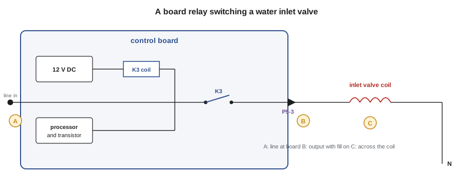
On the morning of Thursday, October 29, before that evening's bench night, Kiran and Dee took a call for a dishwasher that started its cycle, hummed for a minute and then showed a fault code for no water. The customer had already checked that the water supply valve under the sink was open. Dee handed Kiran the tech sheet and asked him to find the fill circuit on the schematic before he took a single panel off. "Two parts decide whether this machine fills," she said, "a relay on the board and a coil on the valve. Find out which one stopped talking to the other."
Relays, solenoids and valves all use the same idea: current through a coil makes a magnetic field, and the field moves something. In a relay, it moves contacts that switch another circuit. In a solenoid, it moves a plunger that locks a door, opens a dispenser or moves a damper. In a valve, it lifts a plunger off a seat to let water flow. This lesson covers how each works, how they fail and how to test them, and shows how to tell a failed control from a failed load.
Coils and magnetic fields
A coil is many turns of fine insulated wire, often around an iron core. When current flows, the coil becomes an electromagnet and pulls on a steel part, called the armature or plunger. When the current stops, a spring returns the part. Coils are rated for a voltage and for AC or DC, and a coil used on the wrong voltage or the wrong kind of current will either fail to pull in or overheat and burn out.
A coil has two kinds of opposition to AC current. Its wire has resistance, which a meter reads with power off. It also has inductance, which opposes changes in current and adds to the total opposition on AC. So an AC coil draws less current than its resistance alone would suggest. A technician tests a coil's resistance against the tech sheet and checks its voltage when it should be energized, rather than predicting its current from Ohm's law.
Relays
A relay is a switch operated by a coil. Its coil circuit and its contact circuit are separate: a small current in the coil switches a much larger current through the contacts. This lets a low-voltage control, such as a control board running on 5 V or 12 V DC, switch a 120 V water valve, a 240 V heater or a motor. A relay's contacts are rated for current and voltage; a relay switching a heating element carries tens of amps, and its contacts are larger than those of a relay switching a valve.
On a control board, most relays have DC coils driven by a transistor that the board's processor switches on. When the board turns on an output, you can often hear the relay click. The relay's contacts are wired to the board's connector pins, and from there to the load. On a schematic, the relay coil is usually drawn inside the board's box, and its contact is drawn on the load's rung, with the same label.
Worked problem
Relay coil current
A board relay has a 12 V DC coil that measures 400 Ω. What current does the board supply to it when the relay is on?
Show solution
- DC coil, so Ohm's law applies directly: I = 12 ÷ 400 = 0.030 A.
Answer: About 30 mA. The board's transistor switches that small current, and the relay contacts can then switch an element drawing 15 A. That separation is why one burned relay contact does not usually damage the processor, and why a board relay that clicks but does not switch the load can have contacts that are burned open even though its coil is good.
Board relays fail in two ways. Contacts can burn open, so the relay clicks but no voltage reaches the load. Or contacts can weld closed after an arc, so the load stays on even when the board turns it off: an oven element that heats when the oven is off, or a valve that keeps filling with the machine unplugged from the board's control. A welded relay that keeps a heater on is a fire hazard, and an appliance with that fault should be left unplugged until it is repaired. On most boards the relays are soldered in, and the repair is a new board; APP-320 covers boards in depth.
Water inlet valves
Washers, dishwashers, refrigerators with water dispensers and ice makers all use solenoid water inlet valves. The coil sits on top of a plastic valve body. When energized, it lifts a plunger, which lets the water pressure open a rubber diaphragm, and water flows. When the coil is off, the plunger drops and the water pressure closes the diaphragm. Most household inlet valves have 120 V AC coils, with a resistance that is typically somewhere between about 500 and 1,500 Ω; some newer appliances use 12 V or 24 V DC valves driven directly by the board. The tech sheet gives the exact value.
Inlet valves fail electrically, with an open or shorted coil, and mechanically, with a blocked inlet screen, a torn diaphragm or a cracked body. A valve with a blocked screen has a good coil and gets voltage but lets through only a trickle. A valve with a torn diaphragm or debris in its seat can leak through when it is off, slowly filling a washer tub or overflowing an ice maker. Many valves also have a flow washer that sets the flow rate; one that has hardened lets too much or too little through.
Worked problem
The dishwasher that would not fill
Following the schematic, Kiran unplugged the dishwasher, removed the lower kick panel and measured the inlet valve coil with its wires disconnected: OL. The tech sheet gives about 900 Ω. To be thorough, he reconnected the wires, restored power and ran the board's service test for the fill output, measuring 120 V across the valve coil terminals. What does that tell him?
Show solution
- Coil resistance OL with power off: the coil is open.
- With the fill commanded, 120 V appears across the coil terminals: the board and its relay are doing their job and sending power to the valve.
- Voltage present but the valve cannot respond because its coil is broken.
Answer: The valve coil had failed open, so the valve never opened, and the board reported no water. Kiran replaced the valve, which on this model came with a new inlet screen, checked the new coil at 905 Ω, ran a fill and watched for leaks at the fittings. If the coil had measured good and the voltage had been missing at the coil, the fault would have been in the wiring or the board, and he would have measured at the board output pin next.
The same logic decides almost every relay-and-load fault: voltage at the load when it should be on, and the load does nothing, means the load has failed. No voltage at the load when it should be on means the fault is upstream, in the relay, the wiring or the control's decision to turn it on. Testing in that order avoids replacing the most expensive part, the board, when the cheap part is at fault.
| Voltage at the load when commanded on | Load resistance with power off | Most likely fault |
|---|---|---|
| Present | OL | Load open: replace the load |
| Present | Correct | Mechanical fault in the load, such as a blocked valve screen or seized motor |
| Absent at the load, present at the board output | Correct | Wiring or connector between the board and the load |
| Absent at the board output | Correct | Relay, board, or the board not commanding the load; check inputs and fault codes |
Solenoids and door locks
Solenoids move things. Front-load washers lock their doors with a solenoid or a small motor-driven lock before filling, and many will not start if the lock does not report that it is locked. Self-cleaning ovens lock their doors with a motorized latch during the clean cycle. Dispensers in refrigerator doors use solenoids to open the ice chute flap. Dishwashers use small solenoids or wax motors to open the detergent cup.
A wax motor is a slow solenoid: a small heater warms a capsule of wax that expands and pushes a plunger over several seconds. Wax motors are used for detergent dispensers, some door locks and some diverter valves. A wax motor reads a resistance like a small heater, often in the range of a few hundred to a few thousand ohms, and it takes several seconds to act, so a technician who expects an instant click will think a good one is dead.
Drain pumps and small synchronous motors
Many washer and dishwasher drain pumps are driven by small permanent-magnet synchronous motors that run directly on 120 V AC. They have a single winding, often reading somewhere in the low tens of ohms, and an impeller that can turn a little freely before it engages, which helps it start. They fail open, with a seized impeller from a foreign object, or with a cracked housing. Lesson 7 showed how a pump drawing several times its rated current is fighting a blockage.
Defrost timers and electromechanical controls
Older refrigerators use a defrost timer, a small synchronous motor that turns a cam. Most of the time, the cam keeps the compressor and fans circuit closed; every 8 to 12 hours of run time, it switches for about 20 to 30 minutes to the defrost heater circuit instead. A defrost timer has four terminals on most models, with a common terminal and separate terminals for the timer motor, the compressor circuit and the defrost circuit; the tech sheet identifies them. A timer stuck in defrost leaves the refrigerator warm with the compressor off; a timer that never reaches defrost lets frost build up, as on the lesson 5 call. A technician can usually turn the timer by hand with a screwdriver to force it into or out of defrost for testing.
Worked problem
Timing the defrost
A refrigerator's defrost timer gives a 25-minute defrost every 10 hours of compressor run time. If the compressor runs 60 in 100 of the time, how often does defrost happen in clock hours, and how long is the heater on per day?
Show solution
- Clock time per 10 h of run time: 10 ÷ 0.60 = 16.7 h.
- Defrosts per day: 24 ÷ 16.7 = 1.44.
- Heater time per day: 1.44 × 25 = 36 minutes.
Answer: About every 16.7 hours by the clock, or about 1.4 times a day, with the heater on for about 36 minutes a day in total. Timers counting run time defrost more often when the compressor runs more, as in hot weather or when the door is opened often.
Testing relays, solenoids and valves safely
With power off, measure coil resistance and compare with the tech sheet. Check relay contacts and solenoid-operated switches for continuity in each position, where they can be reached. With power on, use the appliance's service or test mode where it has one, to command each output, and measure voltage at the load and at the board output. Keep hands clear of moving parts and water when outputs are commanded on, and remember that a commanded valve fills, a commanded pump drains and a commanded heater heats.
Never apply power directly to a coil from a cord with alligator clips to test it, unless the manufacturer's procedure calls for it and you know its voltage and type. A 12 V DC valve coil connected to 120 V AC burns out in moments, and some test cords can make it easy to touch the wrong terminals. Where a direct test is needed, use the correct supply for the coil.
Listening before measuring
Dee's habit before any meter test was to listen. With the appliance in its service mode and an output commanded on, a relay clicks, a valve buzzes faintly and a solenoid thunks. Silence where there should be a click points at the control; a click with no response points at the contacts, the wiring or the load. It is not proof, but it tells you where to put the probes first.
Common mistakes
MistakeReplacing the control board first when a load does not work.
InsteadCheck for voltage at the load first; if it is there, the load has failed.
MistakePredicting an AC coil's current from its resistance.
InsteadAC coils have inductance and draw less; check their resistance and voltage instead.
MistakeCondemning a valve that gets voltage and has a good coil.
InsteadCheck the inlet screen and the water supply; the fault may be mechanical.
MistakeExpecting a wax motor to act instantly.
InsteadWax motors take several seconds to push their plunger.
MistakeLeaving an appliance with a welded relay plugged in.
InsteadA relay stuck closed can keep a heater on; unplug it until it is repaired.
MistakeTesting a DC coil with a 120 V test cord.
InsteadUse the correct voltage and type of supply for the coil, or the appliance's service mode.
Summary and key terms
- A coil makes a magnetic field that moves contacts, a plunger or a valve.
- A relay lets a small coil current switch a large load current; board relays usually have DC coils.
- Board relay contacts can burn open or weld closed; a welded heater relay is a fire hazard.
- Water inlet valves are usually 120 V AC solenoids; they fail with open coils, blocked screens or leaking diaphragms.
- Voltage at the load and no action means the load has failed; no voltage at the load means the fault is upstream.
- Door locks, dispensers and diverters use solenoids, small motors or slow wax motors.
- Use service modes to command outputs and test at the load and the board output.
- Coil
- Turns of insulated wire that become an electromagnet when current flows.
- Relay
- A switch operated by a coil, with the coil circuit separate from the contact circuit.
- Solenoid
- A coil that moves a plunger when energized.
- Water inlet valve
- A solenoid valve that lets water into an appliance when its coil is energized.
- Inductance
- A coil's opposition to changes in current, which reduces AC current below what resistance alone predicts.
- Wax motor
- An actuator in which a small heater expands a wax capsule to push a plunger slowly.
- Defrost timer
- A cam timer that switches a refrigerator between cooling and defrost at set intervals.
- Service mode
- A built-in test routine that lets a technician turn outputs on one at a time.
Practice problems
Work each problem on paper first, then reveal the answer to check.
A board relay's 12 V DC coil measures 600 Ω. What current does it draw?
Show answer
12 ÷ 600 = 0.02 A, or 20 mA.
A valve has 120 V across its coil but no water flows, and the coil reads correctly. What should you check?
Show answer
The inlet screen, the water supply and the valve's mechanical parts.
What does a relay with welded contacts do?
Show answer
It keeps its load on even when the control turns it off.
Why might a good wax motor seem dead?
Show answer
It takes several seconds to move.
A defrost timer stuck in defrost causes what symptom?
Show answer
The refrigerator warms up with the compressor off.
Lesson quiz · 5 questions
Score 60% or more to complete this lesson.
Create a free account to save your progress, take quizzes and earn a certificate.