
APP-120 · Lesson 12 of 12 · 25 min
Tracing a fault on a schematic
▶ Video coming soon A video version of this lesson is on the way.
On Thursday afternoon, November 12, Fenna booked Kiran and Dee into a call she described on the work order as "range, oven slow, smells hot, once quit mid-bake." The customer, Imogen Weller, lived in a brick semi in the Kirkendall neighbourhood with a 2014 freestanding electric range. Dee handed Kiran the work order and the model's tech sheet in the van. "This one's yours," she said. "Schematic first, meter second, parts last. Talk me through it as you go." This lesson follows that call step by step, and draws together every lesson in the course.
Step 1: understand the complaint
At the house, Kiran asked the customer to describe exactly what happened. The oven had been taking about five minutes longer to preheat to 175 °C (350 °F) for a month or so. Twice she had noticed a hot, electrical smell at the back of the range. And on the previous Sunday the oven had stopped heating halfway through roasting a chicken; the display stayed on, and after she switched the oven off and on it heated again. The surface elements worked normally. There was no fault code in the control's history.
Kiran wrote the facts down and drew two conclusions before touching anything. First, the controls and the low-voltage side were working, because the display stayed on and there was no fault code. Second, the fault was intermittent and heat-related: a smell, a slow preheat and an outage that cleared itself pointed to something that heats up, loses contact and recovers, rather than a part that had failed outright. "Intermittent plus a hot smell," he said to Dee. "I'm thinking a connection." She said nothing, which he had learned meant keep going.
Step 2: trace the circuit on the schematic
The tech sheet's schematic showed the bake element on its own rung between L1 and L2. From L1, the path went through a bake relay on the control board, out of the board at connector pin P2-1, along a red wire to one terminal of the bake element. From the element's other terminal, a blue wire ran to a thermal cutout on the back of the oven, then on to the L2 terminal of the range's terminal block. The broil element had a similar rung with its own relay. The oven sensor fed the board on the low-voltage side.
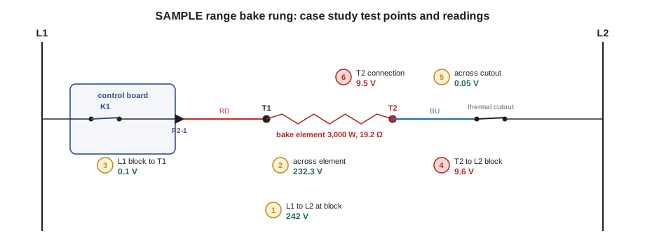
Kiran listed the path as a set of test points, as lesson 3 taught: the supply at the terminal block, the bake relay, the red wire and its terminal at the element, the element itself, the blue wire and its terminal at the element, the thermal cutout, and back to L2. He noted that the relay was on the board and that the board connector P2 also carried low-voltage pins, so he would measure at the element terminals and the terminal block, not at the board, unless the readings sent him there.
Step 3: check the supply
With the range pulled out and its anti-tip bracket released, as APP-110 showed, and the back panel off, Kiran measured at the terminal block with the oven off: L1 to L2 242 V, L1 to N 121 V, L2 to N 121 V, N to ground 0.1 V. The supply was correct. If either leg had been missing, the slow heat and the outage would have had a simpler explanation, and the fault would have belonged to the house wiring.
Step 4: split the circuit in half
The fastest way to find a fault in a long series path is to measure in the middle first, so that each reading rules out half of what is left. This is the split-half method. On the bake rung, the natural middle is the element: measure across it while the oven bakes. If the element has the full supply and draws the right current, the fault is in the element or its behaviour; if the element is short of voltage, the fault is in the path on one side or the other.
Kiran set clamps and probes with the power off, using insulated clips on the element terminals, then restored power and set the oven to bake. After a minute, with the element glowing, he read 232.3 V across the element and 12.1 A on the red lead. The element was rated 3,000 W at 240 V, so its resistance should be 240² ÷ 3,000 = 19.2 Ω, and at 232.3 V it should draw 232.3 ÷ 19.2 = 12.1 A. The current matched. The element was working, but it had about 9.7 V less across it than the 242 V at the terminal block.
Worked problem
Where did 9.7 V go?
The supply is 242 V and the element, 19.2 Ω, has 232.3 V across it while drawing 12.1 A. What resistance is in series with the element, and how much heat is made in it?
Show solution
- Voltage lost outside the element: 242 − 232.3 = 9.7 V.
- Resistance in series: 9.7 ÷ 12.1 = 0.80 Ω.
- \[P = I^2 R = 12.1^2 \times 0.80 = 117\ \text{W}\]
- Element power: 232.3 × 12.1 = 2,811 W, against 242² ÷ 19.2 = 3,050 W with no loss.
Answer: About 0.8 Ω of unwanted resistance somewhere in the path, making about 117 W of heat at that spot and robbing the element of about 240 W. That explained the hot smell and the slower preheat. A good path would lose well under 1 V in total.
Step 5: split again
Next, Kiran measured each half of the path outside the element. From L1 at the terminal block to the element's T1 terminal, through the relay and the red wire, he read 0.1 V: that side was good. From the element's T2 terminal to L2 at the terminal block, through the blue wire and the thermal cutout, he read 9.6 V: the loss was on that side. Splitting that side again, he measured across the thermal cutout: 0.05 V, good. Then across the T2 connection itself, with one probe on the element tab and the other on the blue wire just behind its terminal: 9.5 V.
Nearly all the loss was at one crimp terminal on the element's T2 tab. Kiran switched off at the breaker, proved the range dead, and looked: the terminal was dark brown, its barrel discoloured, and the element tab under it had a blue-black heat mark. When he pulled the terminal off, it came away loosely, and the tab beneath was pitted. On the previous Sunday the connection had presumably heated, expanded and briefly lost contact altogether, which the customer saw as the oven quitting.
Worked problem
Checking the burned terminal with an ohmmeter
With the power off, Kiran measures the burned connection, from the element tab to the blue wire, at 0.3 Ω, which the meter shows as close to good. Why did this reading not reveal the fault on its own?
Show solution
- An ohmmeter passes a tiny current, so a contact that is damaged but still touching can read low.
- Under load, at 12.1 A, the connection heats; its resistance rises to about 0.8 Ω and the drop reaches 9.5 V.
- Only the voltage drop under load showed the real resistance at working current and temperature.
Answer: Because the connection's resistance depends on current and heat. This is the burned-switch lesson from lesson 11 in a real oven: power-off tests miss high-resistance connections, and a voltage drop under load finds them.
Step 6: repair the cause, not just the symptom
The repair had two parts. The element's T2 tab was pitted and heat-damaged, so a new terminal on it would soon fail again; the element had to be replaced. And the blue wire's end had been cooked for weeks, so its copper was dark and its insulation stiff for a short way back. Kiran cut the wire back to bright copper and flexible insulation, crimped on a new high-temperature terminal with the correct crimper, as APP-110 showed, and checked the crimp with a firm pull. He fitted the new element, pushed both terminals fully onto its tabs and made sure they gripped tightly. He also replaced the T1 terminal on the red wire, which was slightly discoloured, because the element supply came with two terminals in the kit.
Before closing up, he checked the parts the heat might have damaged: the thermal cutout read 0.05 V under load, so it was fine, and he checked the insulation of both wires for a short way along the harness. Nothing else had been affected.
Step 7: verify under load
With the range back on its supply, Kiran set the oven to bake and repeated the measurements: across the element 241.6 V; current 12.6 A; across the new T2 connection 0.03 V; L2 side of the path 0.08 V in total. The new element's current matched its resistance: 241.6 ÷ 19.2 = 12.6 A, about 3,040 W. He let the oven preheat to 175 °C (350 °F) and timed it against the tech sheet's typical preheat, which it now met. He checked the broil element's connections while he was there and found them clean.
Worked problem
How much power the repair restored
Before the repair, the element made 2,811 W; after it, 241.6 × 12.6 = 3,044 W. By how much did the repair raise the element's power, and how much heat was no longer being made at the bad connection?
Show solution
- Increase: 3,044 − 2,811 = 233 W, or 233 ÷ 2,811 × 100 = 8.3 in 100 more.
- Heat at the old connection: about 117 W, now about 12.6 × 0.03 = 0.4 W.
Answer: The element now makes about 233 W, or about 8 in 100, more heat, which explains the shorter preheat; and the 117 W that had been cooking the connection is gone. Without the repair, the connection would have kept getting worse until it burned open for good or damaged the harness.
Step 8: explain, document and invoice
Kiran showed the customer the old terminal and the marked element tab, and explained in plain words: a connection at the back of the oven had worn loose, was heating up, and was taking power away from the element; on Sunday it had briefly lost contact. The repair was a new element and new connections, and the oven was now getting its full power. He recommended nothing further, because nothing else was wrong. Dee, watching from the kitchen doorway, noted that he had not used a single word of jargon.
The work order recorded the complaint, the supply readings, the voltage across the element before and after, the 9.5 V drop at the T2 connection, the parts used and the final readings. The invoice was Penfold's 95 dollar service call plus a 165 dollar flat rate for the bake element replacement with terminals, 260 dollars before tax; with 13 in 100 HST, 33.80 dollars, the total was 293.80 dollars. Kiran left at 3:10 p.m., an hour and forty minutes after arriving.
The method, in one list
Driving back to the shop, Dee asked Kiran to say the method out loud, and he did, from his notebook:
- Get the full story of the complaint, including when it happens, smells, sounds and fault codes.
- Find the load on the schematic and list its whole path, both sides, with every switch, protector, wire and connection.
- Check the supply.
- Split the path in half, usually at the load: voltage across it and current through it, with the load on.
- Split the faulty half again, and again, measuring across parts and connections until the loss or the open is in one place.
- Confirm with the power off, and look at the part.
- Fix the cause as well as the failed part, and check for collateral damage.
- Verify under load with the same measurements, and record the before and after readings.
- Explain plainly, document fully, and invoice.
Dee added one thing. "You also did the step that isn't on the list," she said. "You didn't touch the board. Half the technicians in this city would have heard 'quit mid-bake' and ordered a control board before they took the back off." The board on that range cost more than five times the element.
What the course added up to
The call used something from every lesson. Ohm's law and the power formula predicted the element's current and found the unwanted resistance (lesson 1). The series path explained why the voltage was shared between the element and the bad connection (lesson 2). The schematic gave the path and the test points (lesson 3). The 120/240 V supply checks ruled out a missing leg (lesson 4). The thermal cutout was one of the limit controls (lesson 5). The element's rating gave its resistance, and its terminals were the fault (lesson 6). Motors, capacitors, relays, solenoids and valves (lessons 7 to 9) were not involved this time, but the same split-half method finds their faults too. The ground checks confirmed the range was safe to work on and to leave (lesson 10). And the voltage drop under load, rather than the ohmmeter, found the fault (lesson 11).
Kiran's first lead call the next morning would use the same method on a refrigerator. APP-210 and the rest of the program apply these skills to each kind of appliance in turn.
Common mistakes
MistakeOrdering a control board because the oven quit mid-bake.
InsteadTrace and measure first; the fault was a connection worth a fraction of the board's price.
MistakeMeasuring the whole path one point at a time from one end.
InsteadSplit the path in half at the load, then split the faulty half again.
MistakeReplacing only the burned terminal on a damaged element tab.
InsteadA pitted, heat-marked tab will burn the new terminal; replace the element too.
MistakeReusing a wire end that has been overheated.
InsteadCut back to bright copper and flexible insulation before fitting the new terminal.
MistakeLeaving without verifying under load.
InsteadRepeat the voltage and current readings with the load on and record them.
MistakeExplaining the repair in technical terms.
InsteadTell the customer plainly what failed, why, and what was done.
Summary and key terms
- Start with the full complaint: intermittent, heat-related symptoms point to connections and contacts.
- List the load's whole path from the schematic, both sides, before measuring.
- Check the supply, then split the path at the load: voltage across it and current through it.
- Voltage missing across the load is lost somewhere in the path; split the faulty side until it is in one place.
- Unwanted resistance is the lost voltage divided by the current; its heat is I²R.
- Repair the cause and any heat damage, then verify under load with the same measurements.
- Explain plainly, record before and after readings, and invoice.
- Split-half method
- Testing at the middle of a path first, so that each reading rules out half of what remains.
- Intermittent fault
- A fault that comes and goes, often with heat, vibration or moisture.
- Collateral damage
- Damage to nearby parts caused by a fault, such as heat-damaged wire beside a burned terminal.
- Before and after readings
- Measurements recorded before and after a repair to show the fault and prove the fix.
- Test point
- A place on a circuit, listed from the schematic, where a measurement is taken.
Practice problems
Work each problem on paper first, then reveal the answer to check.
An element has 232.3 V across it on a 242 V supply while drawing 12.1 A. What resistance is in series with it?
Show answer
About 0.8 Ω.
Where should the first measurement on a long series path usually be made?
Show answer
Across the load, the middle of the path.
Why was the element replaced along with the terminal?
Show answer
Its tab was pitted and heat-marked and would burn the new terminal.
What did the voltage across the new T2 connection read after the repair?
Show answer
About 0.03 V.
Why did the ohmmeter reading of the burned connection look nearly good?
Show answer
An ohmmeter passes tiny current; the connection's resistance rose under load and heat.
Lesson quiz · 5 questions
Score 60% or more to complete this lesson.
Create a free account to save your progress, take quizzes and earn a certificate.