
APP-110 · Lesson 5 of 12 · 25 min
Using a multimeter and clamp meter
▶ Video coming soon A video version of this lesson is on the way.
On Friday, October 23, Dee set Kiran up at the shop bench with a meter, a box of used parts and a sheet of questions. On the bench were a bake element from an oven, a dryer thermal fuse, a door switch, a washer drain pump and a power strip wired to a test receptacle. "Nobody leaves my van until they can do these five things without thinking," she said. "Prove the meter works. Read a receptacle. Measure a part's resistance. Check a switch. Read the current on a running load. Everything else is the same five things in different places."
The multimeter is the appliance technician's most important diagnostic tool. Almost every electrical fault, whether a burned-out heater, an open switch, a failed motor winding, a missing supply or a bad connection, shows up as a wrong reading of voltage, resistance or current. This lesson covers how to choose a safe meter, how to set it up and how to take the readings an appliance technician uses every day. The electrical theory behind the readings is the subject of APP-120.
Choosing a safe meter: CAT ratings
A meter is safe only if it can survive a voltage spike without failing in your hand. Electrical systems carry brief overvoltages from lightning, switching and motors, and the closer you are to the utility supply, the larger they can be. The international safety standard for test instruments divides measurement locations into categories, and every meter and every set of test leads is marked with the highest category and voltage it is built for:
| Category | Where it applies | Appliance examples |
|---|---|---|
| CAT II | Loads connected to a receptacle | Measurements at a receptacle or inside a plug-in appliance |
| CAT III | Fixed wiring and distribution in the building | Panels, breakers, hard-wired ranges and dryers at their supply |
| CAT IV | The utility supply to the building | The meter base and service entrance; not appliance work |
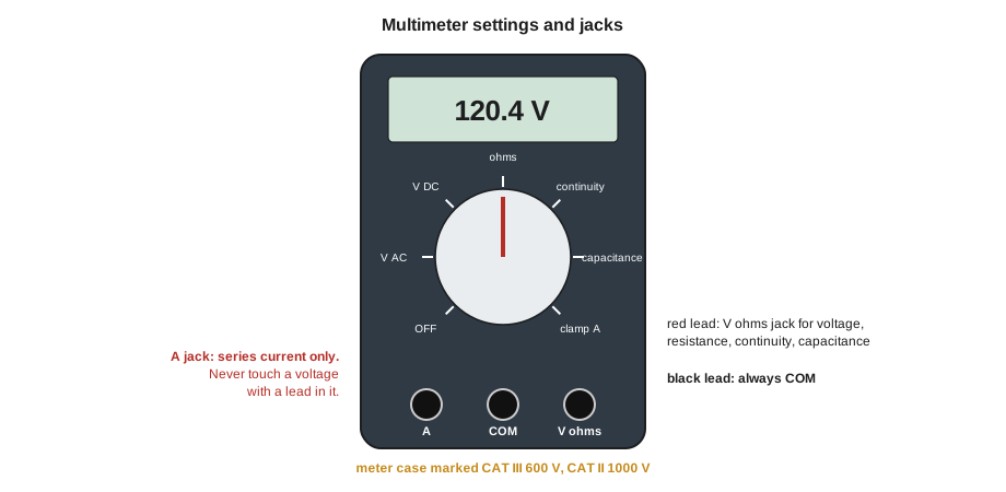
Penfold issues meters rated CAT III 600 V and CAT II 1,000 V, with leads to match. A meter is only as safe as its lowest-rated part, so cheap leads on a good meter make it a cheap meter. Check before every day's work: leads not cut, cracked or melted, probe tips and finger guards intact, the meter case not cracked, and the battery good. A meter with a weak battery can read wrongly.
Setting up and proving the meter
The black lead always goes in the common (COM) jack. For voltage, resistance, continuity and capacitance, the red lead goes in the jack marked with V and Ω. The jack marked A or mA is only for measuring current in series with a circuit, through an internal fuse; plugging a lead into it and then touching a voltage source is a direct short through the meter. Appliance technicians rarely use the A jack; they measure current with the clamp instead.
Before measuring voltage, prove the meter: set it to AC volts and measure a known live source, such as a receptacle known to work or a proving unit in the van. Then take your reading, then measure the known source again. This is the live-dead-live check from lesson 2, and it is the only way to trust a zero reading.
Reading supply voltage
Household supply in Canada is 120/240 V split phase: two hot conductors, each 120 V to the neutral and 240 V to each other, plus a neutral and a ground. Canada's standard for supply voltages, CSA C235, sets a normal range a few volts either side of the nominal 120 and 240 V. Most appliances plug into 120 V receptacles; electric ranges and dryers use a 240 V receptacle or are hard-wired.
At a 120 V receptacle, a technician measures between three pairs of slots: hot to neutral (about 120 V), hot to ground (about 120 V) and neutral to ground (close to 0 V). If hot to neutral is right but hot to ground is zero, the ground is missing. If neutral to ground reads several volts, there may be a loose neutral or a heavy load on the circuit. At a 240 V four-wire range or dryer receptacle, the technician measures L1 to L2 (about 240 V), L1 to neutral and L2 to neutral (about 120 V each) and neutral to ground (close to 0 V).
Worked problem
Reading a dryer receptacle
A dryer runs but does not heat. At its four-wire receptacle Kiran reads L1 to L2: 121 V, L1 to neutral: 121 V, L2 to neutral: 0 V, neutral to ground: 0 V. What do the readings show?
Show solution
- L1 to L2 should be about 240 V; it is only 121 V.
- L2 to neutral should be about 120 V; it is 0 V, so L2 has no voltage.
- L1 is supplying 120 V normally.
Answer: One leg of the 240 V supply is missing, usually a tripped or failed half of the double-pole breaker or a loose connection. The dryer's motor and controls run on 120 V from L1, but the heater needs 240 V, so it cannot heat. This is a supply problem, not a dryer fault: check the breaker, and refer any wiring fault to a licensed electrical contractor.
Measuring resistance and continuity
Resistance and continuity are measured with the power off and the part isolated. The meter sends a small current of its own through the part, so any other voltage in the circuit will give a false reading and can damage the meter. Always unplug, discharge capacitors and, wherever possible, disconnect at least one lead of the part, so that you measure the part alone and not other parts connected in parallel with it.
Resistance readings tell you whether a part is good. Heating elements, motor windings, valve coils and sensors all have a normal resistance listed in the tech sheet or service manual. A reading of OL (over limit) or 1 in the left digit means an open circuit, such as a broken element or a burned winding. A reading much lower than normal can mean a short between turns. For a heating element, the expected resistance can also be worked out from its rating.
Worked problem
Checking a bake element
An oven will not reach temperature. The bake element is rated 3,000 W at 240 V. Kiran disconnects it and measures 19.6 Ω between its terminals and OL from each terminal to the element sheath. Is the element good?
Show solution
- \[R = \frac{V^2}{P}\]
- Expected: R = 240² ÷ 3,000 = 57,600 ÷ 3,000 = 19.2 Ω.
- Measured 19.6 Ω is within about 2 in 100 of 19.2 Ω, which is normal for a cold element.
- OL to the sheath means no short to ground.
Answer: The element is good. The oven fault is elsewhere: the supply, the relay on the control board that switches the element, a wire, or the temperature sensor. A cold element usually reads a little different from the value worked out from its hot rating.
Continuity is a quick yes-or-no version of resistance: the meter beeps when the resistance is low, usually under about 30 to 50 ohms. It is used to check switches, fuses and wires. A thermal fuse or a closed switch should beep and read close to 0 Ω; an open fuse or an open switch reads OL. Check a switch in both positions: a door switch should read close to 0 Ω with the plunger pressed and OL with it released, or the other way round for a normally closed switch.
| Part | Good reading | Faulty reading |
|---|---|---|
| Thermal fuse | About 0 Ω, beeps | OL (open); replace and find why it blew |
| Door or lid switch | About 0 Ω in one position, OL in the other | OL in both, or about 0 Ω in both |
| Heating element | Close to the expected value from the tech sheet | OL (open) or a short to the sheath |
| Motor or pump winding | The tech sheet value, often a few ohms to tens of ohms | OL (open winding) or a short to the frame |
| Wire or harness | About 0 Ω end to end | OL (broken) or a reading to another wire (short) |
Measuring current with a clamp meter
A clamp meter measures current without breaking the circuit. Its jaws sense the magnetic field around a conductor, so the reading is taken by closing the jaws around one conductor. If the jaws go around a whole cord, the current going out on the hot conductor and coming back on the neutral cancel, and the meter reads close to zero. Technicians use a line splitter, a short extension cord with the conductors separated and a loop to clamp around, to measure the current of a plug-in appliance.
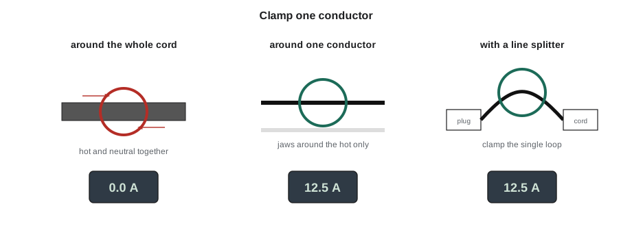
Current readings are taken with the appliance running, so they are live tests: set up the clamp or splitter with power off where you can, keep clear of moving parts, and follow lesson 2. The reading tells you whether a load is drawing what it should. A heater drawing no current is not getting voltage or is open. A motor drawing much more than its rated current may be seized or have a shorted winding. A compressor that draws high current for a few seconds and then trips its overload may have a failed start component.
Worked problem
Expected current of the bake element
With the oven calling for heat, Kiran clamps one of the bake element's leads. What current should he read if the element is getting full voltage, and what would a reading of 0 A mean?
Show solution
- I = V ÷ R = 240 V ÷ 19.2 Ω = 12.5 A.
- Check with power: P = V × I = 240 × 12.5 = 3,000 W, the element rating.
Answer: About 12.5 A. A reading of 0 A with the oven calling for heat means no current is flowing: the element is not getting voltage, because the relay is not closing, a wire is broken or the supply is missing. Since the element measured good, Kiran next checks for voltage at the element terminals with power on.
That afternoon, on a real call, the readings told the story. The customer's oven had baked for twenty years and now took an hour to reach 175 °C. Kiran measured the bake element at 19.4 Ω, good. With power on and the oven calling for heat, his clamp read 12.3 A on the bake element lead, also good. The broil element, which this oven also uses during preheat, read OL: open. Dee showed him the blistered spot on its sheath. A new broil element fixed the preheat time.
Capacitance and other functions
Many meters also measure capacitance, in microfarads. With the capacitor discharged and disconnected, the reading should be within the tolerance printed on the capacitor, often plus or minus 5 or 6 in 100 of the rated value. A run capacitor that reads well below its rating can make a motor run hot or fail to start. Some meters also measure temperature with a thermocouple probe, which is useful for oven and refrigerator checks, and frequency.
Readings you can trust
A meter can mislead as well as inform. Modern digital meters have a very high input impedance, so they can show a voltage of tens of volts on a wire that is disconnected at one end but runs alongside a live wire, picked up by capacitive coupling. This ghost voltage can make a dead wire look live, or a switch look closed. Many meters have a low-impedance (LoZ) mode that loads the circuit slightly and makes ghost voltages disappear; if a reading is surprising, check it in LoZ mode or with the circuit loaded. Other common causes of false readings are a weak battery, a lead not fully seated in its jack, a blown internal fuse in the meter, dirty probe tips and holding the probe tips with your fingers while measuring resistance, which adds your body's resistance to the reading. When a reading does not make sense, check the meter first.
Common mistakes
MistakeMeasuring voltage with a lead in the A jack.
InsteadThe A jack is only for series current; voltage uses the V-Ω jack. Use the clamp for current.
MistakeTrusting a zero voltage reading without proving the meter.
InsteadDo the live-dead-live check every time.
MistakeMeasuring resistance of a part that is still connected to the circuit.
InsteadUnplug, discharge and disconnect at least one lead so that you measure the part alone.
MistakeClamping around a whole cord.
InsteadClamp one conductor, or use a line splitter for plug-in appliances.
MistakeUsing leads with a lower category than the meter.
InsteadA meter is only as safe as its lowest-rated part; match the leads to the meter.
MistakeCondemning a part from one reading without the tech sheet value.
InsteadCompare with the expected value from the tech sheet or the part rating.
Summary and key terms
- Use a meter and leads rated at least CAT III 600 V; inspect them daily.
- Black lead in COM; red in V-Ω for voltage, resistance, continuity and capacitance; the A jack is for series current only.
- Prove the meter with the live-dead-live check before trusting a zero.
- At a receptacle, read hot to neutral, hot to ground and neutral to ground; at 240 V, read L1 to L2 and each leg to neutral.
- Measure resistance and continuity with power off and the part isolated; compare with the tech sheet.
- Clamp one conductor to read current; zero current on a heater means no voltage or an open circuit.
- Multimeter
- A meter that measures voltage, resistance, continuity and often capacitance and current.
- Clamp meter
- A meter that measures current by closing its jaws around a single conductor.
- Measurement category (CAT)
- A rating of the overvoltage a meter can safely withstand at a given location in the electrical system.
- OL
- Over limit; the reading for an open circuit on the resistance range.
- Continuity
- A low-resistance path; the meter beeps when it finds one.
- Line splitter
- An adapter that separates the conductors of a cord so that a clamp meter can read current.
- Split phase
- A 120/240 V supply with two hot conductors, each 120 V to neutral and 240 V to each other.
Practice problems
Work each problem on paper first, then reveal the answer to check.
What category rating should a meter have for work at a panel?
Show answer
At least CAT III, at a voltage of at least 600 V.
What should neutral to ground read at a healthy 120 V receptacle?
Show answer
Close to 0 V.
What is the expected resistance of a 3,000 W, 240 V element?
Show answer
19.2 Ω.
Why must at least one lead of a part be disconnected before measuring its resistance?
Show answer
So that other parts in parallel do not change the reading.
Why does a clamp around a whole cord read zero?
Show answer
The outgoing and returning currents cancel.
Lesson quiz · 5 questions
Score 60% or more to complete this lesson.
Create a free account to save your progress, take quizzes and earn a certificate.