
AERO-310 · Lesson 9 of 12 · 24 min
Stiffened panels
Lesson 8 showed that the first-pass upper cover of the Tern root box would have its skin buckled at about 32 MPa, a tenth of the stress its stringers must carry at ultimate load. That is not a disaster: almost every aircraft compression cover works with buckled skin over much of its flight envelope. But it means the cover has to be analysed and sized as a stiffened panel, a combination of skin and stringers in which the skin buckles early and the stringers, helped by a strip of skin on each side, carry the load to failure. This lesson shows how that works and uses it to choose the Block 2 upper cover.
What happens after the skin buckles
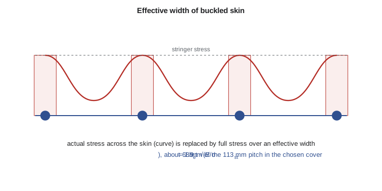
Picture a cover panel under increasing compression. At first the skin and stringers share the load in proportion to their areas, with the same strain everywhere. At the skin's buckling stress, the skin between stringers bows out into waves. From then on, the middle of each skin bay carries little additional stress, because it is already bent; extra load can only be added where the skin is held straight, close to the stringers. The stress across the skin becomes uneven: high next to each stringer, low in the middle of the bay. The stringers pick up an increasing share of the load until they themselves fail, by column buckling, crippling or a combination.
Effective width
Von Kármán proposed a simple way to handle this uneven stress. Replace the real distribution with a uniform stress equal to the stringer stress, acting over an effective width \(b_e\) of skin next to the stringer. He argued that at failure the effective strip behaves like a plate just at its own buckling stress, which gives
for a strip supported on both sides; the constant 1.9 comes from \(\pi/\sqrt{3(1 - \nu^2)}\). The effective width shrinks as the stringer stress grows, so a highly stressed stringer gets less help from the skin. Each stringer then works as a column whose cross-section is its own area plus \(b_e t\) of skin. Variants of the formula, from tests by Sechler and others, adjust the constant, but the principle is unchanged and still underlies most hand methods for stiffened panels.
Panel strength
The strength of a stiffened panel is the strength of its stringer-plus-skin columns. For each stringer, the allowable stress comes from the column curve of Lesson 8, with crippling replacing the yield strength at the short-column end. The panel load is the sum, over stringers and spar caps, of that allowable stress times the stringer area plus its effective skin. Because the effective width depends on the stress, the calculation can be iterated, but one pass with the expected failure stress is usually enough for sizing.
Several failure modes compete, and a good design balances them. If the skin is too thin, the effective width is small and the stringers carry nearly everything. If the stringers are too far apart, the skin buckles early and may wrinkle between rivets. If the ribs are too far apart, the stringers buckle as long columns. If the stringer flanges are too thin, they cripple. The lightest panel is the one in which several of these modes occur at about the same load. Optimization studies of stiffened panels, many of them by NASA and university groups from the 1970s onward, produced design charts that weight engineers still use.
Inter-rivet buckling and wrinkling
Two local failure modes need checking where the skin is riveted to the stringer. Between rivets, the skin can buckle like a short column clamped at each rivet; this inter-rivet buckling sets a maximum rivet pitch, usually several times the skin thickness. And if the stringer flange is thin or flexible, the skin can wrinkle over it, pulling the flange with it. Both are prevented by close enough rivet spacing and a stiff enough stringer flange, details that are settled in the drawings rather than in the panel sizing.
Shear panels and tension fields
Shear behaves similarly. A thin web or skin under shear buckles in diagonal waves, as Lesson 2's Mohr circle predicted: pure shear produces equal tension and compression at 45 degrees, and the compression direction buckles. After buckling, the web carries further shear mainly by diagonal tension, like a set of tension straps running at about 45 degrees. That diagonal tension pulls the flanges or caps together and pushes on the stiffeners, which must be designed for it. Wagner's tension-field theory, developed in the late 1920s, and its later refinements, let designers use thin, light webs that buckle in service and still carry the full load. A tension-field web is lighter than one that must stay flat, but it loads its surroundings more heavily and needs careful fatigue design.
# Stiffened compression panel: effective width of buckled skin and the strength of the upper cover
import math
E, Fcy = 71700.0, 476.0
w, h_avg = 1020.0, 281.0                  # mm, root box width and average depth
M = 420.7e6                               # N mm, ultimate root bending
P_cover = M / h_avg                       # compressive force in the upper cover (caps + stringers + skin)
print(f"Ultimate compression in the upper cover: {P_cover/1e6:.2f} MN")
def effective_width(t, sigma_st):
    return 1.9 * t * math.sqrt(E / sigma_st)            # von Karman, both edges supported
def cover_capacity(t, nstr, Astr, sigma_st, cap=1200.0):
    b = w / (nstr + 1)
    be = min(effective_width(t, sigma_st), b)
    load = nstr * sigma_st * (Astr + be * t) + 2 * sigma_st * (cap + be * t / 2)
    return load, b, be
designs = [("First trial: 1.6 mm skin, 6 Z stringers of 160 mm2", 1.6, 6, 160.0, 328.0),
           ("Second trial (chosen): 2.5 mm skin, 8 Z stringers of 220 mm2", 2.5, 8, 220.0, 345.0),
           ("Alternative: 2.5 mm skin, 9 hat stringers of 250 mm2", 2.5, 9, 250.0, 360.0)]
for lab, t, ns, As, s_allow in designs:
    load, b, be = cover_capacity(t, ns, As, s_allow)
    ms = load / P_cover - 1
    print(f"{lab}\n   stringer pitch {b:.0f} mm, effective skin width {be:.0f} mm, "
          f"capacity {load/1e6:.2f} MN, margin of safety {ms:+.2f}")
# skin shear buckling under the root torque shear flow (from Lesson 5), long panel, ks = 5.35
q = 78.5
for t in (1.6, 2.5):
    b = w / 10
    tau_cr = 5.35 * math.pi ** 2 * E / (12 * (1 - 0.33 ** 2)) * (t / b) ** 2
print(f"Skin {t} mm at {b:.0f} mm pitch: shear buckling {tau_cr:.0f} MPa vs applied {q/t:.0f} MPa")Ultimate compression in the upper cover: 1.50 MN First trial: 1.6 mm skin, 6 Z stringers of 160 mm2 stringer pitch 146 mm, effective skin width 45 mm, capacity 1.27 MN, margin of safety -0.15 Second trial (chosen): 2.5 mm skin, 8 Z stringers of 220 mm2 stringer pitch 113 mm, effective skin width 68 mm, capacity 1.97 MN, margin of safety +0.31 Alternative: 2.5 mm skin, 9 hat stringers of 250 mm2 stringer pitch 102 mm, effective skin width 67 mm, capacity 2.28 MN, margin of safety +0.52 Skin 1.6 mm at 102 mm pitch: shear buckling 87 MPa vs applied 49 MPa Skin 2.5 mm at 102 mm pitch: shear buckling 213 MPa vs applied 31 MPa
The program compares three covers against the ultimate compression of 1.50 MN that the 421 kN m root moment puts into the upper cover. The first trial, with 1.6 mm skin and six Z stringers, has a stringer pitch of 146 mm; its skin contributes only 45 mm of effective width per stringer and the panel carries 1.27 MN, a margin of −0.15. It fails the requirement. The second trial uses 2.5 mm skin and eight Z stringers of 220 mm², which closes the pitch to 113 mm, raises the effective width to 68 mm and lifts the capacity to 1.97 MN, a margin of +0.31. A third option with nine hat stringers reaches +0.52, but at extra weight that the target cannot afford. Marcus approves the second trial, noting that its margin will shrink a little once the detailed analysis adds rivet holes, joggles and fuel-tank sealant to the picture. The thicker skin also helps in shear: it no longer buckles under the torsion shear flow at all.
For the lower cover, which is in tension, buckling is not the issue. Its thickness will be set by fatigue and damage tolerance, the subject of Lesson 10, and the lower cover usually ends up thinner than the upper one, in a more fatigue-resistant alloy.
Integral panels and modern practice
The Tern's covers are built-up: skins riveted to separate extruded stringers. Many modern aircraft machine their covers from thick plate, leaving the stringers as integral blades, or bond them, or make them of carbon fibre composite with co-cured stringers. Integral panels save the weight and labour of thousands of fasteners and avoid inter-rivet buckling, but a crack in an integral panel can run straight from skin into stringer with nothing to stop it, so their damage tolerance must be designed in with crack-arrest features. Composite panels, covered in Lesson 11, are usually designed not to buckle below limit load at all, because buckling in a composite can start delaminations. The effective-width ideas remain useful in all of these, but the allowables come from tests on the specific construction.
Checking the chosen cover along the span
A cover that works at the root must also work everywhere else. Outboard, the bending moment falls quickly, as Lesson 1 showed, and so does the compression in the upper cover. The structures team therefore steps the cover down along the span: the skin thins at chosen rib stations, stringers run out one by one as the box narrows, and the spar caps lose area in machined steps. Each change is a place where load must transfer from one member to another, and each is checked. Where a stringer ends, its load passes into the skin and neighbouring stringers through the fasteners near its tip, so stringer run-outs are tapered and given extra fasteners to avoid a sudden concentration that could start a fatigue crack. Where the skin changes thickness, the step is placed on a rib, so that the thinner panel starts with a supported edge.
Arjun repeats the panel calculation at four stations, using the moments from the Lesson 1 program and the local box depth. At 25 percent span, where the moment has fallen to about 230 kN m, the cover can drop to 2.0 mm skin with seven stringers and still show a margin above +0.2. At half span, 1.6 mm skin and five stringers are enough. Beyond about 75 percent span, minimum gauge and the loads from the aileron hinges govern rather than overall bending. Plotting the margin along the span shows the usual saw-tooth pattern of a well-designed cover: margins rise between stations and fall back to a small positive value just outboard of each step, which is a sign that material is being used efficiently.
The same check reveals a subtle point about rib spacing. The rib pitch sets the column length of the stringers. Near the root, where the stringer stress is highest, ribs at 500 mm keep the stringers in the Johnson range with a good allowable. Further out, wider rib spacing would save rib weight but would lower the stringer allowable just where the cover has become thinner. The team keeps a constant 500 mm pitch across the box, which also simplifies tooling and assembly.
Worked problem
Effective width of a skin
A 2.0 mm skin is attached to stringers whose stress at failure is 300 MPa. Find the effective width with \(E\) = 71.7 GPa.
Show solution
- \(b_e = 1.9 \times 2.0 \times \sqrt{71\,700/300}\).
- \(= 3.8 \times 15.46 = 58.7\) mm.
Answer: Each stringer gets about 59 mm of skin working with it at failure. If the stringer pitch is 150 mm, about 40 percent of the skin is effective.
Worked problem
Panel capacity
A cover has ten stringers of 200 mm² and 2.0 mm skin, with a stringer allowable of 330 MPa. Using the effective width at that stress, estimate the panel load, ignoring spar caps.
Show solution
- \(b_e = 1.9 \times 2 \times \sqrt{71\,700/330} = 56.0\) mm, so each column has \(200 + 56.0 \times 2 = 312\) mm².
- Panel load: \(10 \times 330 \times 312 = 1.03\) MN.
Answer: The skin adds more than half again to the stringer area at failure, even though it buckled long before.
Common mistakes
MistakeCounting the full skin width in a buckled compression panel.
InsteadUse the effective width at the stringer failure stress.
MistakeDesigning the skin not to buckle at all in a metal cover.
InsteadMetal covers are usually allowed to buckle well below ultimate; the stringers carry the load.
MistakeIgnoring inter-rivet buckling and wrinkling.
InsteadCheck rivet pitch and flange stiffness so the skin cannot fail locally.
MistakeTreating a tension-field web as if it carried pure shear on its surroundings.
InsteadDiagonal tension loads the caps and stiffeners; design them for it.
Summary and key terms
- In a stiffened compression panel, the skin buckles early and the stringers carry the load to failure, helped by an effective width of skin b_e = 1.9t√(E/σ_st).
- The panel strength is the sum of stringer allowable stresses times stringer plus effective skin area.
- Competing modes include column buckling, crippling, inter-rivet buckling and wrinkling.
- Shear webs carry load after buckling by diagonal tension.
- For the Tern root upper cover, the first-pass 1.6 mm layout fails (MS −0.15); 2.5 mm skin with eight stringers gives +0.31.
- Stiffened panel
- A skin reinforced by stringers, designed as a unit.
- Effective width
- The width of buckled skin assumed to carry the full stringer stress.
- Inter-rivet buckling
- Buckling of skin between adjacent rivets.
- Wrinkling
- Local failure in which skin and a thin stringer flange buckle together.
- Tension field
- The diagonal tension that carries shear in a buckled web.
- Integral panel
- A cover machined or formed with its stringers as one piece.
Practice problems
Work each problem on paper first, then reveal the answer to check.
Find the effective width of 1.6 mm skin at a stringer stress of 250 MPa.
Show answer
1.9 × 1.6 × √(71 700/250) = 51.5 mm.
Why does the effective width shrink as the stringer stress rises?
Show answer
A narrower strip buckles at a higher stress, matching the stringer stress at failure.
In the program, change the first trial to 2.0 mm skin. What is its margin?
Show answer
The capacity rises to about 1.36 MN, a margin of about −0.10, so it still fails.
Why might a composite cover be designed not to buckle below limit load?
Show answer
Buckling can start delaminations between plies.
What does diagonal tension in a web do to the stiffeners?
Show answer
It compresses them and loads the caps inward.
Name one disadvantage of integral panels.
Show answer
Cracks can run from skin into stringer without a natural crack stopper.
Lesson quiz · 5 questions
Score 60% or more to complete this lesson.
Create a free account to save your progress, take quizzes and earn a certificate.