
AERO-310 · Lesson 4 of 12 · 23 min
Shear flow in open sections
Bending stresses come from the bending moment; shear stresses come from its rate of change along the span, the shear force. In a solid rectangular beam the shear stress follows the familiar parabola, peaking at the middle of the depth. In a thin-walled section the shear must travel along the walls, and the useful quantity is no longer the shear stress but the shear flow: the shear force per unit length of wall, \(q = \tau t\), in newtons per millimetre. Marcus explains to Arjun that the whole of wing box shear analysis is bookkeeping with shear flow, and that once the bookkeeping is clear, the method works for any shape. This lesson starts with open sections, which have a free edge where the bookkeeping can begin.
Why shear flow
Consider a small piece of wall cut from a thin-walled beam, of length \(\delta z\) along the beam and running from a free edge to a point \(s\) along the wall. The bending stress on its two ends is slightly different, because the bending moment changes along the beam. The difference must be balanced by a shear force on the cut face. Since the wall is thin, the shear stress is nearly uniform through the thickness and acts along the wall, so the force per unit length of beam is the shear flow at \(s\). Equilibrium gives
For a section symmetric about the x axis, with vertical shear only, this simplifies to \(q(s) = -(S_y/I_{xx})\int_0^s ty\,ds\). The integral is the first moment of the wall area between the free edge and the point \(s\), the same quantity that appears in solid-beam shear formulae. Shear flow starts at zero at a free edge, because there is nothing for it to act on, and builds up as the integral accumulates area.
Shear flow has one very useful property: at a junction where walls meet, the flows in must equal the flows out, just like water at a pipe junction. That is the origin of the name. It makes the analysis of complex sections a matter of following the walls and keeping track of what enters and leaves each junction.
A channel spar
The Tern's rear spar, at its simplest, is a channel: a web 258 mm deep with flanges 60 mm wide, all 3 mm thick. Under a vertical shear, the shear flow starts at zero at the tip of the top flange and grows linearly along it, because every bit of flange is at the same height. At the corner it turns down into the web, where it keeps growing, but more slowly near the neutral axis, so the web distribution is parabolic with its peak at the middle. Below the neutral axis the material is in compression rather than tension, so the integral starts to decrease, and the flow falls back to zero at the tip of the bottom flange.
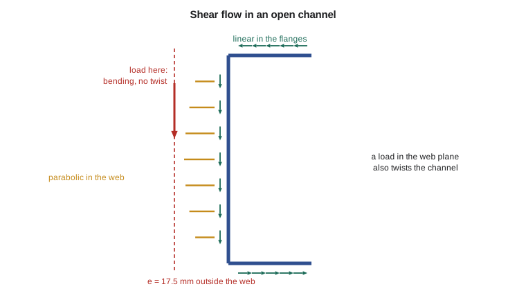
The flange flows are horizontal, one pointing toward the web at the top and one pointing away at the bottom. They form a couple. The web flow is vertical and equal to the applied shear. The resultant of all the shear flows is therefore a vertical force equal to \(S_y\), but it does not act through the web: the couple from the flanges moves it to a line outside the section, on the side away from the flanges.
The shear centre
That line defines the shear centre, the point through which a shear load must pass for the section to bend without twisting. If the load passes anywhere else, it also applies a torque about the shear centre, and the section twists. For sections with two axes of symmetry, such as an I-beam or a rectangular box with equal walls, the shear centre is at the centroid. For a channel it lies outside the web. For an angle or a T, made of walls meeting at a point, it is at that point, because all the shear flows act through it and have no moment about it.
For a channel with flanges of width \(b\), web depth \(h\) and uniform thickness, taking moments of the flange forces about the web gives the classic result
Finding the shear centre is the main reason for computing open-section shear flows in practice. A load applied away from it twists open sections easily, because an open thin wall is very weak in torsion: its torsion constant is only \(\sum bt^3/3\), which for thin walls is tiny. A channel loaded through its web will rotate and may fail by combined bending and twisting long before its bending strength is reached. Purlins, stringers and the edge members of cutouts are all designed with this in mind.
# Shear flow in an open channel section and the position of its shear centre
h, bf, t = 258.0, 60.0, 3.0          # mm: web depth, flange width, thickness (rear spar as a channel)
Sy = 40e3                            # N, vertical shear through the shear centre
Ixx = t * h**3 / 12 + 2 * bf * t * (h / 2) ** 2
print(f"Ixx = {Ixx/1e6:.2f}e6 mm4")
n = 400
# walk the wall: top flange tip -> web top -> web bottom -> bottom flange tip
pts = [(bf - bf * i / n, h / 2) for i in range(n + 1)] + [(0, h / 2 - h * i / n) for i in range(1, n + 1)] \
      + [(bf * i / n, -h / 2) for i in range(1, n + 1)]
q = [0.0]
for k in range(1, len(pts)):
    (x1, y1), (x2, y2) = pts[k - 1], pts[k]
    ds = ((x2 - x1) ** 2 + (y2 - y1) ** 2) ** 0.5
    q.append(q[-1] - Sy / Ixx * t * (y1 + y2) / 2 * ds)
qf = q[n]; qmax = min(q)
print(f"Shear flow at the flange-web corner: {abs(qf):.1f} N/mm; at mid-web: {abs(qmax):.1f} N/mm")
print(f"Shear flow at the far flange tip (should be about zero): {q[-1]:.4f} N/mm")
print(f"Peak web shear stress {abs(qmax)/t:.1f} MPa; average web shear Sy/(h t) = {Sy/(h*t):.1f} MPa")
# moment of the flange shear flows about the web centre line gives the shear centre offset e
F = 0.0
for k in range(1, n + 1):
    F += (q[k - 1] + q[k]) / 2 * (bf / n)     # force carried by the top flange
e = 2 * abs(F) * (h / 2) / Sy
print(f"Flange force {abs(F)/1000:.2f} kN each; shear centre {e:.1f} mm outside the web")
print(f"Formula 3 b^2 / (h + 6 b) = {3 * bf**2 / (h + 6 * bf):.1f} mm")
# a load through the web instead of the shear centre twists the section
T = Sy * e
print(f"Load applied in the web plane adds a torque of {T/1e6:.2f} kN m about the shear centre")Ixx = 10.28e6 mm4 Shear flow at the flange-web corner: 90.3 N/mm; at mid-web: 187.4 N/mm Shear flow at the far flange tip (should be about zero): -0.0000 N/mm Peak web shear stress 62.5 MPa; average web shear Sy/(h t) = 51.7 MPa Flange force 2.71 kN each; shear centre 17.5 mm outside the web Formula 3 b^2 / (h + 6 b) = 17.5 mm Load applied in the web plane adds a torque of 0.70 kN m about the shear centre
The program confirms the shape described above. The shear flow at the flange-web corner is 90 N/mm and at mid-web 187 N/mm, so the peak web shear stress, 62.5 MPa, is about 21 percent above the average value of shear force divided by web area. The flow returns to zero at the bottom flange tip, a useful check that the integration has been done correctly. Each flange carries a force of 2.7 kN, and their couple places the shear centre 17.5 mm outside the web, exactly matching the formula. If the 40 kN were applied in the plane of the web, it would also twist the channel with a torque of 0.7 kN m.
Where open sections appear in an airframe
Wing boxes and fuselages are closed, but much of the structure inside them is open. Stringers are Zs, hats, Js or angles. Ribs and frames are often channels or Zs, with lightening holes cut in their webs. Spars of light aircraft are sometimes channels or I-sections without a closed box. In each case the shear centre matters whenever the member carries shear without a skin that holds it straight. Before the skin is attached, during assembly, or when a skin panel has buckled and can no longer restrain the stringer, these members are prone to twisting. That is one reason stress engineers check stringer stability in the post-buckled state, as Lesson 9 shows.
A further subtlety is warping. When an open section twists, its plane cross-sections do not stay plane: points move along the beam by different amounts. If the ends are free to warp, the section twists easily. If an end is restrained, for example where a stringer is clamped at a rib or a spar is built into a root fitting, warping restraint creates additional direct stresses and makes the section stiffer in torsion near the restraint. Detailed models capture this; hand analysis usually ignores it and accepts that the result is slightly conservative for twist.
Combining bending and shear in a spar
In the Tern's rear spar the shear flows of this lesson act together with the bending stresses of Lesson 3. At the junction between web and flange, both are significant: the flange carries most of the bending stress and the web carries most of the shear. For a quick check of a spar section, engineers compute the bending stress in the flanges from the bending moment, the shear flow in the web from the shear force, and then check the corner region, where both act, with the von Mises criterion of Lesson 2. The rivets or the machined radius joining web and flange must also carry the shear flow that passes between them, which for the rear spar at the root is about 90 newtons on every millimetre of the joint.
Worked problem
Shear centre of a channel stringer
A channel stringer has a web 40 mm deep and flanges 15 mm wide, all 1.6 mm thick. Where is its shear centre?
Show solution
- \(e = 3b^2/(h + 6b) = 3 \times 15^2/(40 + 90) = 675/130\).
- \(e = 5.2\) mm outside the web.
Answer: Small, but not zero. If the stringer carried shear from a load attached to its web, it would also see a small torque.
Worked problem
Peak shear stress in an I-section spar
An I-section spar has a web 250 mm deep and 2.5 mm thick and flanges 50 mm wide and 6 mm thick. It carries a vertical shear of 30 kN. Find the shear flow where the web meets the flange and at mid-web.
Show solution
- \(I_{xx} \approx 2.5 \times 250^3/12 + 2 \times 50 \times 6 \times 125^2 = 3.26 \times 10^6 + 9.38 \times 10^6 = 12.6 \times 10^6\) mm⁴.
- First moment of one flange: \(50 \times 6 \times 125 = 37\,500\) mm³. Web-flange junction: the flows from both half-flanges add, so \(q = 30\,000 \times 37\,500/12.6 \times 10^6 = 89\) N/mm.
- Add the upper half of the web: \(2.5 \times 125 \times 62.5 = 19\,500\) mm³, total 57 000 mm³, so \(q = 136\) N/mm at mid-web, a stress of 54 MPa.
Answer: Because the flanges hold most of the first moment, the web shear is nearly uniform. That is why the simple average \(S/(ht)\), 48 MPa here, is often a good first estimate for spar webs.
Common mistakes
MistakeStarting the shear flow integral at an arbitrary point in an open section.
InsteadStart at a free edge, where the shear flow is known to be zero.
MistakeAssuming the shear centre is always at the centroid.
InsteadOnly for doubly symmetric sections. For a channel it lies outside the web.
MistakeForgetting that a load away from the shear centre also twists the section.
InsteadResolve the load into a shear through the shear centre plus a torque.
MistakeIgnoring the junction rule.
InsteadShear flows into a junction must equal those leaving it.
Summary and key terms
- Shear in thin walls is described by shear flow q = τt, which follows from the change in bending stress along the beam.
- In an open section it starts at zero at a free edge and accumulates the first moment of area along the wall.
- Flows balance at junctions.
- The resultant of the shear flows acts through the shear centre, where a shear load causes bending without twisting.
- For a channel it lies outside the web at e = 3b²/(h + 6b).
- Open sections are very weak in torsion, so loads that miss the shear centre can twist them badly.
- Shear flow
- Shear force per unit length of wall, q = τt.
- Shear centre
- The point through which a shear load causes bending without twisting.
- Open section
- A thin-walled section with at least one free edge and no enclosed cell.
- First moment of area
- The integral of distance times area, which drives the shear flow.
- Warping
- Axial displacement of points in a cross-section when the section twists.
- Torsion constant
- The measure of a section's stiffness in twisting; for open thin walls about Σbt³/3.
Practice problems
Work each problem on paper first, then reveal the answer to check.
What is the shear flow at the free tip of a flange?
Show answer
Zero.
Where is the shear centre of an equal-leg angle?
Show answer
At the corner where the two legs meet.
For a channel with h = 200 mm and b = 50 mm, find e.
Show answer
e = 3 × 2500/(200 + 300) = 15 mm.
Why are open sections weak in torsion?
Show answer
Their torsion constant, Σbt³/3, is tiny for thin walls.
In the program, double the flange width. What happens to e?
Show answer
It increases to about 3 × 120²/(258 + 720) = 44 mm.
Three walls meet at a junction carrying 40 N/mm in and 15 N/mm out on the second wall. What flows out on the third?
Show answer
25 N/mm.
Lesson quiz · 5 questions
Score 60% or more to complete this lesson.
Create a free account to save your progress, take quizzes and earn a certificate.