
AERO-310 · Lesson 7 of 12 · 23 min
Fuselage analysis
The Tern flies low enough that its cabin is not pressurized, but Borealis Aerospace is also studying a larger aircraft: the Swift 900, a light twin-turbofan business jet designed to cruise at Mach 0.80 at 12 500 m. Dr. Kenji Watanabe's high-speed group has already shaped its wing. At that altitude the outside air pressure is about 18 kPa, and to keep the cabin at an altitude of about 1800 m the fuselage must hold a pressure difference of about 63 kPa. Marcus asks Arjun to spend part of his term on the first fuselage sizing for the Swift, because a pressurized fuselage is the clearest example in aerospace of a structure whose design is driven by fatigue rather than by its static strength.
The fuselage as a pressure vessel
A pressurized fuselage is, first of all, a thin-walled cylinder holding internal pressure. Equilibrium of half the cylinder gives the hoop stress, which acts around the circumference, and equilibrium of the end cap gives the longitudinal stress, which acts along the length.
The hoop stress is twice the longitudinal stress, which is why a pressure vessel that fails by overpressure splits along its length. In a fuselage the frames, spaced about 500 mm apart, share some of the hoop load with the skin, and the stringers share some of the longitudinal load, so the skin stresses are a little lower than these formulae give. The simple values are still the starting point and are usually within 10 to 20 percent.
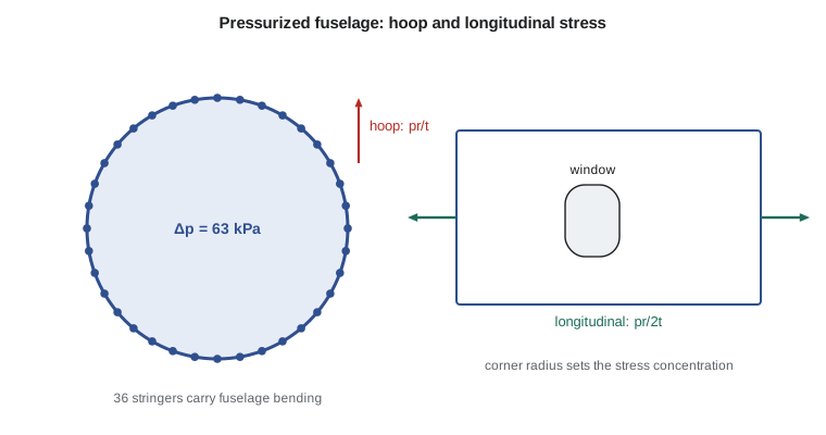
For the Swift, with a radius of 875 mm and a 1.2 mm skin of 2024-T3 aluminium, the operating hoop stress is only about 46 MPa. That sounds very low, and statically it is. the standards for transport category aeroplanes in Chapter 525 of the Transport Canada Airworthiness Manual require the pressurized structure to carry the maximum relief valve pressure multiplied by an extra factor of 1.33, in addition to the usual factor of safety, and to carry pressure combined with flight loads. Even with a factor of 2.0 in total, the hoop stress at ultimate is under 100 MPa, less than a quarter of the material's ultimate strength.
Why the skin is not thinner
If static strength set the thickness, the Swift's skin could be about half a millimetre thick. It is not, for three reasons. First, a skin that thin would be easily damaged by hail, dropped tools, baggage carts and service vehicles, and would be hard to rivet or bond. Most manufacturers set a minimum gauge, typically around 0.8 to 1.0 mm for a fuselage, below which they will not go regardless of the stress. Second, the fuselage must also resist bending and torsion from flight and landing loads, which add stresses that pressure alone does not show. Third, and most important, every flight is one full cycle of pressurization: the skin is loaded to its operating hoop stress and unloaded again, tens of thousands of times over the aircraft's life. Fatigue cracks grow under that cycling, so the operating hoop stress is held to a level that gives a long fatigue life and slow crack growth, often in the range of about 90 to 110 MPa for aluminium fuselages of this kind. Around windows and doors it is held much lower than that.
The lessons of fuselage fatigue were learned at great cost. In 1954 two de Havilland Comet airliners broke up in flight within a few months. Investigations, including a full fuselage tested in a water tank to many cycles of pressure, found that fatigue cracks had started at the corners of cutouts in the cabin roof and grown until the fuselage failed suddenly. The cutouts had sharp corners and the skin around them carried high cyclic stresses. Since then, fuselages have used rounded window corners, thicker doublers around cutouts, crack-stopping straps and frames, and full-scale fatigue tests. The requirements for fatigue and damage tolerance in section 525.571 of the Airworthiness Manual, and their equivalents for smaller aircraft, grew out of these and later accidents.
Fuselage bending
The fuselage is also a beam, supported at the wing and loaded by the weight of everything in it and by the tail loads. In flight at a high load factor, or in a hard landing, the parts ahead of and behind the wing bend downward, putting the crown in tension and the keel in compression. Fuselage bending is analysed with the idealized methods of Lesson 6: the stringers, with their share of the skin, become booms around the circle, and the frames hold the circle in shape. For a ring of \(n\) equal booms of area \(B\) at radius \(r\), the second moment of area is \(nBr^2/2\), and the stress at the crown and keel is \(Mr/I\).
The crown stringers therefore see tension from bending added to tension from pressure, and at the keel compression from bending is partly offset by pressure. Frames carry the hoop load where they are attached, keep the stringers from buckling, and distribute concentrated loads from the wing, the landing gear and the tail into the shell. They are designed as curved beams and can be the heaviest parts of the fuselage.
Cutouts
Windows, doors, hatches and access panels interrupt the shell. Around each cutout the load that would have passed through the missing skin must flow around it, which concentrates stress at the edges and especially at the corners. For a circular hole in a wide plate in uniform tension, the stress concentration factor \(K_t\) is 3; around a rectangular cutout with small corner radii it can be much higher. Designers use generous corner radii, oval windows, thickened skin or doublers around the edge, and heavy frames and longerons on each side of a door to carry the interrupted loads. Large doors also break the closed section, so the structure around them must restore the shell's ability to carry torsion and shear, as Lesson 5 explained.
# Swift 900 fuselage: pressurization stresses, fuselage bending with stringers, and a window corner
import math
r = 875.0                 # mm, fuselage radius
t = 1.2                   # mm, 2024-T3 skin
dp = 0.063                # MPa, maximum normal operating cabin differential (63 kPa)
hoop = dp * r / t; longi = dp * r / (2 * t)
print(f"Operating pressure {dp*1000:.0f} kPa: hoop stress {hoop:.1f} MPa, longitudinal {longi:.1f} MPa")
f_ult = 1.33 * 1.5        # extra pressure factor times the factor of safety
print(f"Ultimate pressure case (x{f_ult:.2f}): hoop {hoop*f_ult:.1f} MPa against about 434 MPa ultimate")
for s_target in (90, 110):
    print(f"   skin needed to keep operating hoop stress at {s_target} MPa: {dp*r/s_target:.2f} mm")
# fuselage bending: 36 equally spaced stringers, each with 100 mm2 plus the skin idealized into booms
ns, As = 36, 100.0
pitch = 2 * math.pi * r / ns
B = As + t * pitch           # each boom gets one pitch of skin (uniform stress ratio around a circle averages out)
I = ns * B * r * r / 2
M = 260e6                    # N mm, ultimate down-bending just aft of the wing (hard landing / gust)
s_top = M * r / I
print(f"\nBoom area {B:.0f} mm2, I = {I/1e9:.2f}e9 mm4")
print(f"Ultimate bending stress at the crown {s_top:.1f} MPa (tension), keel {-s_top:.1f} MPa (compression)")
# the crown also carries longitudinal pressure stress when the cabin is pressurized
print(f"Crown at 1g flight with pressure: about {s_top/(1.5*2.5) + longi:.1f} MPa")
# a window cutout: stress concentration at the corner
for rc, Kt in ((10, 4.0), (40, 2.7), (80, 2.2)):
    print(f"   corner radius {rc:3d} mm, Kt about {Kt}: peak hoop stress {Kt*hoop:6.1f} MPa each flight")
cycles_per_year, years = 1100, 25
print(f"\nDesign life target: {cycles_per_year*years} pressurization cycles ({cycles_per_year}/year for {years} years)")Operating pressure 63 kPa: hoop stress 45.9 MPa, longitudinal 23.0 MPa Ultimate pressure case (x2.00): hoop 91.6 MPa against about 434 MPa ultimate skin needed to keep operating hoop stress at 90 MPa: 0.61 mm skin needed to keep operating hoop stress at 110 MPa: 0.50 mm Boom area 283 mm2, I = 3.90e9 mm4 Ultimate bending stress at the crown 58.3 MPa (tension), keel -58.3 MPa (compression) Crown at 1g flight with pressure: about 38.5 MPa corner radius 10 mm, Kt about 4.0: peak hoop stress 183.8 MPa each flight corner radius 40 mm, Kt about 2.7: peak hoop stress 124.0 MPa each flight corner radius 80 mm, Kt about 2.2: peak hoop stress 101.1 MPa each flight Design life target: 27500 pressurization cycles (1100/year for 25 years)
The program shows the whole argument in a few lines. At 63 kPa the hoop stress is 46 MPa and the longitudinal stress 23 MPa. At ultimate pressure the hoop stress is 92 MPa, well within the strength of the skin. Holding the operating hoop stress to 90 MPa would need only 0.6 mm of skin, which is why the Swift's 1.2 mm is set by minimum gauge, damage resistance and fatigue around cutouts rather than by pressure. The ultimate bending case adds 58 MPa at the crown. The window corners tell the real story: with a small 10 mm corner radius the peak hoop stress would reach about 184 MPa on every flight, a stress that would start cracks within the design life. With an 80 mm radius it drops to about 101 MPa. For a design life of 27 500 pressurization cycles, 1100 flights a year for 25 years, Arjun recommends large-radius window corners with a machined doubler, a decision that Lesson 10's fatigue methods will confirm.
Floors, bulkheads and the rest of the shell
The pressure shell ends at two bulkheads, one behind the cockpit or radome and one at the rear of the cabin. A flat bulkhead must resist the full pressure by bending, so it needs heavy stiffeners; a domed bulkhead carries pressure by membrane tension and can be much lighter. The cabin floor, supported on beams attached to the frames, carries passengers and baggage and must also withstand the pressure difference that appears if one compartment loses pressure suddenly while the other does not. Venting paths between cabin and cargo areas, sized so that the floor does not collapse during a sudden decompression, are a design requirement for pressurized aircraft. Each of these items has its own load cases and its own margins, and together they make the fuselage a far more varied structure than the wing.
Arjun's sizing note for the Swift ends with a list of items for the next phase: the window belt with its doublers, the frames around the main entry door, the rear pressure bulkhead and the floor venting areas. Each will need its own detailed analysis, and each will be checked against the fatigue and damage tolerance requirements before the fuselage design is frozen.
Worked problem
Skin thickness for a target hoop stress
A regional aircraft fuselage has a radius of 1.35 m and an operating pressure difference of 55 kPa. The designers want the operating hoop stress to stay below 95 MPa. What skin thickness is needed?
Show solution
- \(t = \Delta p\, r/\sigma_h = 0.055 \times 1350/95\).
- \(t = 0.78\) mm.
Answer: Minimum gauge and local reinforcement will probably set a thicker skin. The pressure check shows that the shell has plenty of static strength.
Worked problem
Crown stress in a fuselage
A fuselage of radius 1.0 m has 40 stringer booms of 280 mm² each. At a bending moment of 400 kN m, what is the crown stringer stress? Add the longitudinal pressure stress for 60 kPa and a 1.2 mm skin.
Show solution
- \(I = nBr^2/2 = 40 \times 280 \times 1000^2/2 = 5.6 \times 10^9\) mm⁴.
- Bending: \(\sigma = 400 \times 10^6 \times 1000/5.6 \times 10^9 = 71.4\) MPa.
- Longitudinal pressure stress: \(0.06 \times 1000/(2 \times 1.2) = 25.0\) MPa.
- Total at the crown: about 96 MPa in tension.
Answer: Pressure and bending add at the crown. The same structure at the keel sees about 46 MPa in compression.
Common mistakes
MistakeSizing a fuselage skin from static pressure strength alone.
InsteadFatigue, minimum gauge, damage resistance and cutout stresses usually govern.
MistakeUsing the longitudinal stress formula for the hoop direction.
InsteadHoop stress is pr/t, twice the longitudinal pr/2t.
MistakeIgnoring the stress concentration at window and door corners.
InsteadCorners can raise the local stress several times; generous radii and doublers are essential.
MistakeTreating a door cutout as though the shell were still closed.
InsteadThe structure around a door must restore the closed load path for torsion and shear.
Summary and key terms
- A pressurized fuselage carries hoop stress pr/t and longitudinal stress pr/2t.
- For the Swift 900, 63 kPa gives only 46 MPa of hoop stress in a 1.2 mm skin, so static strength is not critical.
- Thickness is set by minimum gauge, damage resistance and, above all, fatigue from one pressure cycle per flight, especially at cutout corners, as the Comet accidents showed.
- Fuselage bending is analysed with stringer booms; pressure and bending add at the crown.
- Bulkheads, floors and venting complete the design.
- Hoop stress
- The circumferential stress in a pressurized cylinder, Δp r/t.
- Longitudinal stress
- The axial stress in a closed pressurized cylinder, Δp r/2t.
- Minimum gauge
- The thinnest skin a manufacturer will use, regardless of calculated stress.
- Doubler
- An extra layer of skin added around a cutout or fitting to reduce local stress.
- Pressure bulkhead
- The structure that closes the pressurized shell at each end.
- Stress concentration factor
- The ratio of peak local stress to the nominal stress, K_t.
Practice problems
Work each problem on paper first, then reveal the answer to check.
What is the hoop stress for Δp = 60 kPa, r = 1.0 m and t = 1.0 mm?
Show answer
60 MPa.
For the same fuselage, what is the longitudinal stress?
Show answer
30 MPa.
A circular window in a skin with a nominal hoop stress of 40 MPa has K_t = 3. What is the peak stress?
Show answer
120 MPa.
Why are domed pressure bulkheads lighter than flat ones?
Show answer
They carry pressure by membrane tension instead of bending.
In the program, raise the operating differential to 70 kPa. What is the new hoop stress?
Show answer
70/63 × 45.9 ≈ 51 MPa.
Name two design features introduced after the Comet accidents.
Show answer
Rounded window corners, doublers and crack-stopping straps, and full-scale fatigue testing.
Lesson quiz · 5 questions
Score 60% or more to complete this lesson.
Create a free account to save your progress, take quizzes and earn a certificate.