
AERO-310 · Lesson 1 of 12 · 27 min
Loads on aircraft structures
The aerodynamics group at Borealis Aerospace has finished the shape of the Tern Block 2 wing: a taper ratio of 0.45, 2.5 degrees of washout, NACA 4415 sections at the root and 4412 at the tip, and double-slotted flaps. Now the wing has to be built. Marcus Webb, who leads the structures group, has asked Arjun Mehta to spend his final co-op work term on the structural design of the new wing box, from the loads at the start to the finite element model at the end. Élise Fournier, the chief engineer, has set one firm target: the new wing must weigh no more than the Block 1 wing it replaces, even though it is longer, carries more fuel and has bigger flaps. Every kilogram saved in structure is a kilogram of payload or fuel. That target is why aircraft structures are designed differently from bridges or buildings, and why this course spends so much time on thin walls, buckling and fatigue.
Before a single skin thickness can be chosen, the engineer must know what the structure has to carry. This first lesson sets out where aircraft loads come from, how the rules turn them into design cases, and how lift and weight along the span become the shear forces and bending moments that the rest of the course uses.
Limit loads, ultimate loads and the factor of safety
Aircraft rules work with two levels of load. Limit loads are the largest loads the aircraft is expected to meet in service: the highest manoeuvre load factor a pilot may command, the strongest gust the design is expected to fly through, the hardest landing that counts as normal. Under limit load the structure must not deform permanently or in a way that affects safe operation. Ultimate loads are the limit loads multiplied by a factor of safety, which for civil aircraft is 1.5. Under ultimate load the structure must not fail, although it may yield. For the Tern, whose limit manoeuvre load factor is +3.09, the ultimate load factor is therefore 4.64.
The factor of 1.5 is not a margin for sloppy analysis. It covers variability that cannot be removed: scatter in material properties, small differences between drawings and the parts built, loads that slightly exceed the predicted values, and the gradual effects of age and environment. Because it is applied to loads rather than to stresses, it works the same way whether a part yields, buckles or fractures. Material strength values are handled separately: the design uses statistically based allowables, A-basis values for parts whose failure would be catastrophic with no other path for the load, and B-basis values for redundant structure, so that a factor of safety does not have to make up for weak material as well.
For the Tern, these requirements come from the airworthiness standards Transport Canada applies to commuter aeroplanes (Chapter 523 of the Airworthiness Manual). A future business jet study, which appears later in this course, would fall under the standards for transport category aeroplanes in Chapter 525 of the Transport Canada Airworthiness Manual. The two sets of standards share the same basic approach to limit loads, ultimate loads and the 1.5 factor, although the details of load cases and of fatigue and damage tolerance differ.
The flight envelope: manoeuvres and gusts
The V-n diagram, which you met in AERO-220, is the structural engineer's map of flight loads. It plots load factor against equivalent airspeed and shows the combinations the aircraft must withstand. On the left, the curved boundary is set by the stall: at low speed the wing simply cannot produce enough lift to reach a high load factor. The curve meets the limit manoeuvre load factor of 3.09 at the design manoeuvring speed \(V_A\), 305 km/h for the Tern. From there the envelope runs flat to the design dive speed \(V_D\), 415 km/h. On the negative side, the limit is −1.23, reached at a lower speed because the wing makes less lift upside down, and it tapers back to zero at \(V_D\).
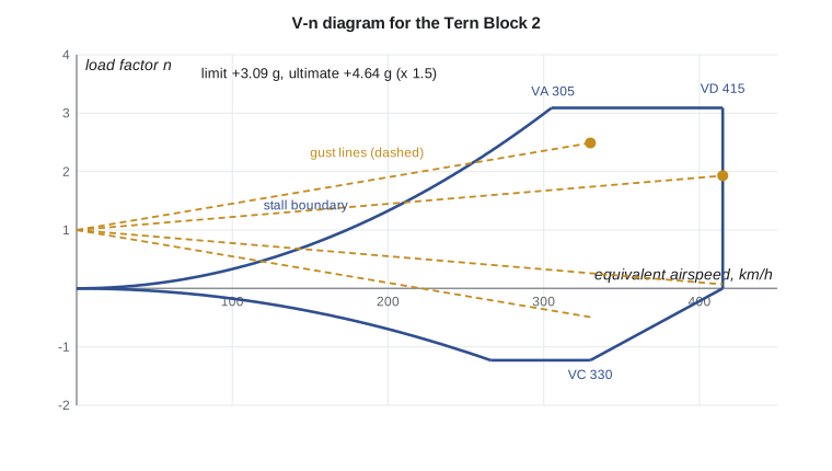
Gusts add a second set of cases. When the aircraft flies into a vertical gust of speed \(U\), the angle of attack jumps by about \(U/V\), and the lift jumps with it. The Pratt formula, used in many design standards, turns this into a load factor increment. It includes an alleviation factor \(K_g\) that accounts for the aircraft starting to rise before the gust has fully acted, which depends on a mass ratio \(\mu\) comparing the aircraft's wing loading with the air it displaces.
The design gust speeds are set by the rules: about 15.2 m/s of equivalent gust at the design cruise speed \(V_C\) and half that at \(V_D\), at the lower altitudes. For a light, slow aircraft with a modest wing loading, gusts can produce larger load factors than manoeuvres. For the Tern, at 6500 kg and 28 square metres, they come close: the program below finds 2.49 at \(V_C\) and 1.93 at \(V_D\), a little below the AERO-220 estimate because the Block 2 wing has a slightly lower lift slope. The manoeuvre case of 3.09 therefore sizes most of the wing, but the gust cases must still be checked everywhere, and for the tail and the engine mounts they can govern.
Other sources of load
Flight loads are only one family. A complete loads report for a commuter aircraft contains hundreds of cases, which the structures team groups by the part they affect most.
| Source | What it loads most | Typical design question |
|---|---|---|
| Symmetric manoeuvres and gusts | Wing box, fuselage bending, wing-to-fuselage joint | Root bending moment and shear at the highest load factor |
| Asymmetric manoeuvres (rolling, yaw) | Wing torsion, fin, rear fuselage | Torque on the wing box when the ailerons are deflected at speed |
| Landing and ground handling | Landing gear, gear attachments, fuselage keel | Peak loads at touchdown, braking and turning on the ground |
| Cabin pressure | Fuselage skin, frames, doors and windows | Hoop stress and the number of pressure cycles over the life |
| Powerplant | Engine mounts, nacelles, wing local structure | Thrust, torque and the loads if a propeller blade is lost |
| Control surfaces | Hinges, actuators, local wing and tail structure | Hinge moments at full deflection and high speed |
| Inertia and crash | Seats, cargo restraints, heavy items of equipment | Holding items in place during an emergency landing |
Arjun's first job is narrower: the symmetric flight cases for the wing box. These produce the largest bending moments and shear forces at the wing root, and they size most of the spars and covers.
From lift to shear force and bending moment
Along the span, the wing carries lift upward and its own weight, the weight of fuel and the weight of anything mounted on it downward. At a load factor \(n\), all of the weights are multiplied by \(n\) too, because the structure must accelerate them. The net upward load per metre of span, integrated from the tip inward, gives the shear force at each section. Integrating the shear force inward again gives the bending moment.
Here \(l\) is the lift per unit span, \(m'\) the mass per unit span and \(s\) the semi-span. The weight of the wing and its fuel acts against the lift, which reduces the root bending moment. This effect is called inertia relief, and it is the reason designers like to keep fuel in the wing for as long as possible during a flight and to burn the fuselage tanks first.
The spanwise distribution of lift comes from the aerodynamic analysis, ideally from a lifting-line or panel method like those in AERO-300. In early design a simple estimate is often enough. Schrenk's method takes the average of two shapes: one proportional to the local chord, and one elliptical with the same total lift. It gives a good approximation for straight, untwisted wings without needing any aerodynamic calculation, and the structures team uses it to size the first layout while the aerodynamicists refine the real distribution.
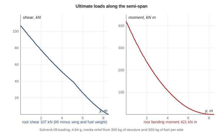
# Loads on the Tern Block 2 wing: gust load factors, then shear and bending along the semi-span
import math
g, m, S, b = 9.81, 6500.0, 28.0, 17.0
W = m * g; WS = W / S
a = 5.04                   # finite-wing lift slope per radian (AERO-300: about 0.088 per degree)
c_mac = 1.73
rho0 = 1.225
def gust_n(V_eas, Ude):
    mu = 2 * WS / (rho0 * c_mac * a * g)
    Kg = 0.88 * mu / (5.3 + mu)
    return 1 + Kg * rho0 * Ude * V_eas * a / (2 * WS), mu, Kg
for name, V_kmh, Ude in (("VC", 330, 15.24), ("VD", 415, 7.62)):
    n, mu, Kg = gust_n(V_kmh / 3.6, Ude)
    print(f"{name} {V_kmh} km/h EAS, gust {Ude:5.2f} m/s: mass ratio {mu:4.1f}, alleviation {Kg:.3f}, n = {n:.2f}")
n_lim = 3.09; FS = 1.5; n_ult = n_lim * FS
print(f"Limit manoeuvre factor {n_lim}, ultimate {n_ult:.3f}")
# Schrenk spanwise loading on one wing (semi-span 8.5 m), root chord 2.27 m, tip 1.02 m
s_half = b / 2; cr, ct = 2.27, 1.02
N = 170
dy = s_half / N
ys = [(i + 0.5) * dy for i in range(N)]
chord = lambda y: cr + (ct - cr) * y / s_half
area = sum(chord(y) * dy for y in ys)
Lhalf = n_ult * W / 2
lift = []
for y in ys:
    trap = Lhalf * chord(y) / area
    ell = 4 * Lhalf / (math.pi * s_half) * math.sqrt(1 - (y / s_half) ** 2)
    lift.append(0.5 * (trap + ell))              # N per metre of span
# inertia relief: wing structure 350 kg per side spread with chord, fuel 550 kg per side inboard of 60 % span
wing_m, fuel_m, yfuel = 350.0, 550.0, 0.6 * s_half
inert = []
for y in ys:
    w = wing_m * chord(y) / area
    f = fuel_m / yfuel if y < yfuel else 0.0
    inert.append(n_ult * g * (w + f))
net = [l - i for l, i in zip(lift, inert)]
def shear_moment(q):
    V = M = 0.0
    out = []
    for k in range(N - 1, -1, -1):          # integrate from the tip inward
        V += q[k] * dy
        M += V * dy
        out.append((ys[k] - dy / 2, V, M))
    return out[::-1]
for lab, q in (("lift only", lift), ("lift minus wing and fuel inertia", net)):
    sm = shear_moment(q)
    print(f"{lab:34s}: root shear {sm[0][1]/1000:6.1f} kN, root bending moment {sm[0][2]/1000:6.1f} kN m")
sm = shear_moment(net)
for frac in (0.0, 0.25, 0.5, 0.75):
    k = int(frac * N)
print(f" y = {sm[k][0]:4.2f} m shear {sm[k][1]/1000:6.1f} kN moment {sm[k][2]/1000:6.1f} kN m")VC 330 km/h EAS, gust 15.24 m/s: mass ratio 43.5, alleviation 0.784, n = 2.49 VD 415 km/h EAS, gust 7.62 m/s: mass ratio 43.5, alleviation 0.784, n = 1.93 Limit manoeuvre factor 3.09, ultimate 4.635 lift only : root shear 147.8 kN, root bending moment 544.5 kN m lift minus wing and fuel inertia : root shear 106.9 kN, root bending moment 420.7 kN m y = 0.00 m shear 106.9 kN moment 420.7 kN m y = 2.10 m shear 75.7 kN moment 228.8 kN m y = 4.25 m shear 48.2 kN moment 95.8 kN m y = 6.35 m shear 21.4 kN moment 20.8 kN m
The results show how much inertia relief matters. With lift alone, the root bending moment at ultimate load would be 545 kN m. Including 350 kg of wing structure and 550 kg of fuel in each wing reduces it to 421 kN m, about 23 percent less. That number, 421 kN m at the root, is the starting point for the wing box design in Lessons 3 to 9. The shear force of 107 kN will size the spar webs.
There is a catch, which the loads team handles carefully. Inertia relief only helps if the fuel is actually there. A case with the wing tanks nearly empty and a full fuselage payload produces a larger root bending moment, so the design must cover the range of possible fuel states, not just the one that suits the structure. The loads report therefore runs the same manoeuvre at several weights and fuel loadings, and the envelope of all of them is what the structure must carry.
Torsion and the position of the loads
Lift does not act along a convenient line through the wing box. On a cambered section, the aerodynamic centre sits near the quarter chord and carries a nose-down pitching moment; when the flaps or ailerons are deflected, that moment grows. The weight of fuel and structure acts near the middle of the box, and the engine nacelles hang far forward. The structure resists all of these offsets as torsion about the shear centre of the wing box, a point you will meet in Lesson 4. Arjun's loads summary for the root gives an ultimate torque of about 45 kN m, which the closed wing box carries through shear flow in its skins and spar webs, as Lesson 5 shows.
Worked problem
Gust load factor by hand
Check the Tern's gust load factor at \(V_C\) = 330 km/h equivalent airspeed with the design gust of 15.24 m/s. Use \(W/S\) = 2277 N/m², mean chord 1.73 m and lift slope 5.04 per radian at sea-level density.
Show solution
- Mass ratio: \(\mu = 2 \times 2277/(1.225 \times 1.73 \times 5.04 \times 9.81) = 43.5\).
- Alleviation factor: \(K_g = 0.88 \times 43.5/(5.3 + 43.5) = 0.784\).
- Speed: 330 km/h is 91.7 m/s.
- Increment: \(\Delta n = 0.784 \times 1.225 \times 15.24 \times 91.7 \times 5.04/(2 \times 2277) = 1.49\), so \(n = 2.49\).
Answer: The gust load factor of 2.49 is below the manoeuvre limit of 3.09, so the manoeuvre case sizes the wing root. A lighter aircraft or a higher cruise speed could reverse that result.
Worked problem
Root bending moment from a simple distribution
Estimate the root bending moment of one Tern wing at the ultimate load factor if the net load were uniform along the 8.5 m semi-span, and compare it with the program's result.
Show solution
- Net ultimate load on one wing: the program gives a root shear of 106.9 kN, which is the total net load outboard of the root.
- For a uniform load the resultant acts at mid-span, so \(M = 106.9 \times 8.5/2 = 454\) kN m.
- The program's value, with lift concentrated inboard and the fuel weight relieving the inner wing, is 421 kN m.
Answer: A uniform load overestimates the moment by about 8 percent here. Simple estimates are useful as checks, but the distribution matters, and real design uses the best spanwise loading available.
Common mistakes
MistakeApplying the 1.5 factor of safety to material strengths instead of to loads.
InsteadThe factor multiplies limit loads to give ultimate loads. Material strengths are covered separately by statistically based allowables.
MistakeIgnoring inertia relief, or assuming the fuel is always in the wing.
InsteadWeight in the wing reduces root bending only when it is there. Check the fuel states that give the worst case.
MistakeTreating the gust cases as minor because the manoeuvre factor is larger.
InsteadGust loads are compared location by location. They can govern the tail, the engine mounts and the outer wing even when manoeuvres govern the root.
MistakeForgetting that weights are multiplied by the load factor.
InsteadAt 4.64 g, a 550 kg fuel load pushes down with more than 25 kN on each wing.
Summary and key terms
- Aircraft structures are designed to limit loads, the largest expected in service, and must survive ultimate loads, which are 1.5 times larger.
- The V-n diagram combines manoeuvre and gust load factors; the Pratt formula estimates gust increments.
- Lift minus the weight of structure and fuel, multiplied by the load factor, integrates to the shear force and bending moment along the span.
- Schrenk's method gives a quick lift distribution.
- For the Tern Block 2 at ultimate load, the root shear is about 107 kN and the root bending moment about 421 kN m, with roughly 45 kN m of torque.
- Limit load
- The largest load expected in service; the structure must not deform permanently under it.
- Ultimate load
- The limit load multiplied by the factor of safety of 1.5; the structure must not fail under it.
- Load factor
- The ratio of lift to weight, n.
- Gust alleviation factor
- A factor in the gust formula that accounts for the aircraft responding before the gust has fully acted.
- Inertia relief
- The reduction in wing bending caused by the weight of structure and fuel acting against the lift.
- Schrenk method
- An approximate lift distribution taken as the average of a chord-shaped and an elliptical distribution.
- A-basis allowable
- A material strength value that at least 99 percent of the population is expected to exceed, with 95 percent confidence.
Practice problems
Work each problem on paper first, then reveal the answer to check.
The Tern's limit negative load factor is −1.23. What is the ultimate negative load factor?
Show answer
−1.23 × 1.5 = −1.85.
If the root bending moment at 1 g is 90 kN m, roughly what is it at the limit load factor of 3.09?
Show answer
About 3.09 × 90 = 278 kN m, since lift and weights both scale with n.
Why do designers burn fuselage fuel before wing fuel?
Show answer
Keeping fuel in the wing preserves inertia relief and reduces wing bending for most of the flight.
How does the gust load factor change if the wing loading doubles, other things equal?
Show answer
The increment falls, roughly in proportion to 1/(W/S), though the alleviation factor rises a little.
In the program, remove the fuel (set fuel_m to 0). What happens to the root bending moment?
Show answer
It rises toward the lift-only value, because less weight relieves the wing.
Name two load families that matter more to the fuselage than to the wing.
Show answer
Cabin pressure and landing or ground handling loads.
Lesson quiz · 5 questions
Score 60% or more to complete this lesson.
Create a free account to save your progress, take quizzes and earn a certificate.