
AERO-310 · Lesson 11 of 12 · 23 min
Composite laminates
The Block 2 wing keeps an aluminium box, but its new flaps and ailerons will be carbon fibre composite. Élise's weight target made the case: the composite control surfaces save about 30 kilograms over metal ones, and they are not in the main fatigue-critical load path, which makes them a sensible first step for a company that has built mostly metal aircraft. Marcus asks Arjun to work with the composites specialist on the aileron spar, and in doing so to learn how composite structure is analysed and why its certification follows a different path from metal.
Fibres, matrix and the lamina
A carbon fibre composite is made of very stiff, strong fibres held in a polymer matrix, usually an epoxy. The fibres carry the load; the matrix holds them in place, transfers load between them and protects them. A single layer, or lamina, with all its fibres in one direction is extremely stiff and strong along the fibres and weak across them. A typical unidirectional carbon/epoxy tape has a modulus of about 135 GPa along the fibres and only about 10 GPa across them, with a shear modulus of about 5 GPa. That anisotropy is both the advantage and the challenge of composites: the designer can put stiffness exactly where it is needed, but must also make sure that no direction is left too weak.
For a thin lamina in plane stress, Hooke's law takes an orthotropic form with four independent constants, \(E_1\), \(E_2\), \(G_{12}\) and \(\nu_{12}\), written in the fibre axes 1 and 2. The stiffness matrix \(\mathbf{Q}\) relates stresses to strains in those axes. A lamina laid at an angle \(\theta\) to the structural axes has a transformed stiffness \(\bar{\mathbf{Q}}(\theta)\), found by rotating stresses and strains. At angles other than 0 and 90 degrees, \(\bar{\mathbf{Q}}\) has terms that couple normal stress to shear strain: pulling an angled lamina makes it shear.
Laminates and classical lamination theory
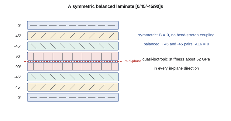
Real parts are laminates: stacks of laminae at different angles, typically 0, +45, −45 and 90 degrees. Classical lamination theory assumes that the laminate behaves like a thin plate, with strains varying linearly through the thickness, and adds up the contributions of each ply. The result relates the in-plane force resultants \(\mathbf{N}\) (force per unit width) and moment resultants \(\mathbf{M}\) to the mid-plane strains \(\boldsymbol{\varepsilon}^0\) and curvatures \(\boldsymbol{\kappa}\) through three matrices.
The \(\mathbf{A}\) matrix gives in-plane stiffness, \(\mathbf{D}\) bending stiffness and \(\mathbf{B}\) the coupling between them. Two simple layup rules keep laminates well behaved. A symmetric laminate, the same above and below the mid-plane, has \(\mathbf{B} = 0\), so it does not bend or twist when pulled and does not warp when it cools from the curing temperature. A balanced laminate, with every +θ ply matched by a −θ ply, has \(A_{16} = A_{26} = 0\), so in-plane tension does not cause shear. Almost all aircraft laminates are both. Designers also follow rules such as using at least about 10 percent of plies in each of the four main directions, so the laminate has some strength in every direction, and avoiding too many plies of the same angle stacked together.
# Classical lamination theory: ABD matrices and effective stiffness of carbon/epoxy laminates
import math
E1, E2, G12, v12, tp = 135e3, 10e3, 5e3, 0.30, 0.125     # MPa and mm, typical unidirectional carbon/epoxy tape
v21 = v12 * E2 / E1
d = 1 - v12 * v21
Q11, Q22, Q12, Q66 = E1 / d, E2 / d, v12 * E2 / d, G12
def qbar(th):
    c, s = math.cos(math.radians(th)), math.sin(math.radians(th))
    c2, s2 = c * c, s * s
    return [[Q11*c2*c2 + 2*(Q12 + 2*Q66)*s2*c2 + Q22*s2*s2, (Q11 + Q22 - 4*Q66)*s2*c2 + Q12*(s2*s2 + c2*c2), (Q11 - Q12 - 2*Q66)*s*c*c2 + (Q12 - Q22 + 2*Q66)*s*s2*c],
            [0, Q11*s2*s2 + 2*(Q12 + 2*Q66)*s2*c2 + Q22*c2*c2, (Q11 - Q12 - 2*Q66)*s*s2*c + (Q12 - Q22 + 2*Q66)*s*c*c2],
            [0, 0, (Q11 + Q22 - 2*Q12 - 2*Q66)*s2*c2 + Q66*(s2*s2 + c2*c2)]]
def abd(layup):
    n = len(layup); h = n * tp
    A = [[0.0] * 3 for _ in range(3)]; B = [[0.0] * 3 for _ in range(3)]; D = [[0.0] * 3 for _ in range(3)]
    for k, th in enumerate(layup):
        z0 = -h / 2 + k * tp; z1 = z0 + tp
        Q = qbar(th)
        for i in range(3):
            for j in range(i, 3):
                A[i][j] += Q[i][j] * (z1 - z0); B[i][j] += Q[i][j] * (z1**2 - z0**2) / 2; D[i][j] += Q[i][j] * (z1**3 - z0**3) / 3
    for M in (A, B, D):
        for i in range(3):
            for j in range(i): M[i][j] = M[j][i]
    return A, B, D, h
def inv3(M):
    a, b, c = M[0]; d_, e, f = M[1]; g, h, i = M[2]
    det = a*(e*i - f*h) - b*(d_*i - f*g) + c*(d_*h - e*g)
    return [[(e*i - f*h)/det, (c*h - b*i)/det, (b*f - c*e)/det],
            [(f*g - d_*i)/det, (a*i - c*g)/det, (c*d_ - a*f)/det],
            [(d_*h - e*g)/det, (b*g - a*h)/det, (a*e - b*d_)/det]]
for name, lay in (("quasi-isotropic [0/45/-45/90]s", [0, 45, -45, 90, 90, -45, 45, 0]),
                  ("spar cap [0/45/0/-45/0/90]s", [0, 45, 0, -45, 0, 90, 90, 0, -45, 0, 45, 0]),
                  ("unbalanced [0/45]2 (a layup to avoid)", [0, 45, 0, 45])):
    A, B, D, h = abd(lay)
    a = inv3(A)
    Ex, Ey, Gxy = 1 / (a[0][0] * h), 1 / (a[1][1] * h), 1 / (a[2][2] * h)
    bmax = max(abs(x) for r in B for x in r)
    print(f"{name}: {len(lay)} plies, {h:.2f} mm")
    print(f"   Ex = {Ex/1000:5.1f} GPa, Ey = {Ey/1000:5.1f} GPa, Gxy = {Gxy/1000:4.1f} GPa, A16 = {A[0][2]:8.0f} N/mm, "
          f"largest B term {bmax:7.0f} N")
# strain check for the composite aileron spar cap: running load Nx = 600 N/mm at ultimate
for lay in ([0, 45, 0, -45, 0, 90, 90, 0, -45, 0, 45, 0],
            [0, 45, 0, 0, -45, 0, 90, 0, 0, 90, 0, -45, 0, 0, 45, 0]):
    A, B, D, h = abd(lay); a = inv3(A)
    ex = a[0][0] * 600
print(f"Aileron spar cap, {len(lay)} plies: strain at ultimate {ex*1e6:.0f} microstrain (design value 4000)")quasi-isotropic [0/45/-45/90]s: 8 plies, 1.00 mm Ex = 52.4 GPa, Ey = 52.4 GPa, Gxy = 20.0 GPa, A16 = 0 N/mm, largest B term 0 N spar cap [0/45/0/-45/0/90]s: 12 plies, 1.50 mm Ex = 79.9 GPa, Ey = 40.0 GPa, Gxy = 15.0 GPa, A16 = 0 N/mm, largest B term 0 N unbalanced [0/45]2 (a layup to avoid): 4 plies, 0.50 mm Ex = 74.8 GPa, Ey = 13.7 GPa, Gxy = 10.3 GPa, A16 = 7865 N/mm, largest B term 1452 N Aileron spar cap, 12 plies: strain at ultimate 5004 microstrain (design value 4000) Aileron spar cap, 16 plies: strain at ultimate 3202 microstrain (design value 4000)
The quasi-isotropic laminate [0/45/−45/90]s has the same in-plane modulus, about 52 GPa, in every direction, a little below aluminium at less than 60 percent of the density. The spar cap layup, with half its plies at 0 degrees, reaches 80 GPa along the span at the cost of lower stiffness across it. Both are symmetric and balanced, so the program finds zero coupling terms. The unbalanced [0/45]₂ layup shows what the rules prevent: a large \(A_{16}\), meaning it shears when pulled, and non-zero \(\mathbf{B}\) terms, meaning it bends and twists when loaded in its plane or cooled after curing. A part made that way would warp out of the mould.
Strength and failure
Composite failure is more complex than metal yielding. A lamina can fail by fibre fracture, by matrix cracking, by shear between fibres or, in a laminate, by delamination between plies. Criteria such as maximum stress, maximum strain, Tsai-Wu and Hashin compare ply stresses with ply strengths for each mode. For design, the aircraft industry often uses laminate-level strain allowables instead, typically a few thousand microstrain, chosen to cover the effects of holes, impact damage and the environment. These are much lower than the strain at which a pristine coupon fails, because composites are sensitive to damage in ways metals are not.
The aileron spar cap illustrates the method. Under the ultimate hinge and bending loads it carries a running load of 600 N/mm. The twelve-ply cap, 1.5 mm thick, reaches 5000 microstrain, above the 4000 microstrain design value the composites specialist has set for this construction. A sixteen-ply cap with more zero-degree plies brings it down to 3200 microstrain, a comfortable margin, for a weight increase of about 200 grams per aileron.
Damage, environment and certification
Three features of composites shape how they are certified. First, impact damage can be nearly invisible: a dropped tool can crush the matrix inside a laminate and cause delaminations while leaving only a faint mark on the surface. The concept of barely visible impact damage, the largest damage that a reasonable inspection might miss, is central: the structure must carry ultimate load with it present. Second, heat and moisture soften the matrix. Allowables are therefore measured hot and wet, with the material conditioned to its end-of-life moisture content and tested at the highest service temperature, and these environmental knockdowns can be large for matrix-dominated properties. Third, composites show much more scatter and are less well understood than metals, so their certification relies on a building-block approach: many coupon tests, then elements, then subcomponents and finally full-scale components, with analysis validated at each level.
The FAA's advisory circular AC 20-107B, Composite Aircraft Structure, sets out accepted methods for all of these, and Transport Canada's guidance for composite structure follows the same principles. For the Tern's control surfaces, Borealis Aerospace will show static strength with damage present, fatigue and damage growth behaviour, repair methods and protection against lightning, since carbon fibre does not conduct as well as aluminium and needs added conductive layers to carry strike currents safely.
Composites also change the fatigue picture. Unlike metals, well-designed carbon laminates are very resistant to fatigue at typical stress levels, and damage tends to grow slowly or not at all under normal loads. The concern shifts from crack growth to impact damage, manufacturing defects and environmental degradation, which is why inspections of composite parts focus on damage detection rather than crack tracking. Where composite parts meet metal, galvanic corrosion is a risk: carbon in contact with aluminium accelerates its corrosion, so the two are separated with fibreglass layers or sealants, or titanium fasteners and fittings are used.
Manufacturing and quality
Composite parts are made by laying up plies, often pre-impregnated with resin, on a mould and curing them under heat and pressure, usually in an autoclave. The quality of the cured part depends on the process: voids, wrinkles, ply misalignment and resin-rich or resin-poor areas all reduce strength. Every production part is therefore inspected, usually by ultrasonic scanning, and the process itself is qualified so that parts made later behave like the test articles used for certification. Repairs follow approved procedures, typically bonded or bolted patches, and are designed with the same allowables and damage assumptions as the original part.
Worked problem
Effective modulus from the A matrix
A symmetric laminate 2.0 mm thick has \(a_{11}\) = 5.0 × 10⁻⁶ mm/N from the inverse of its A matrix. What is its effective modulus \(E_x\)?
Show solution
- \(E_x = 1/(a_{11} h) = 1/(5.0 \times 10^{-6} \times 2.0)\).
- \(= 100\,000\) MPa, or 100 GPa.
Answer: The inverse of A, scaled by the thickness, gives the effective engineering constants of a laminate.
Worked problem
Strain under a running load
A quasi-isotropic laminate 3.0 mm thick with \(E_x\) = 52 GPa carries a running load of 400 N/mm. What is the strain, and is it within a 3500 microstrain allowable?
Show solution
- Stress: \(400/3.0 = 133\) MPa.
- Strain: \(133/52\,000 = 2.56 \times 10^{-3}\), or 2560 microstrain.
- Margin against 3500 microstrain: \(3500/2560 - 1 = +0.37\).
Answer: Strain-based allowables are convenient because the same allowable applies regardless of the layup's stiffness.
Common mistakes
MistakeUsing an unsymmetric or unbalanced layup for a flat part.
InsteadUse symmetric and balanced stacks so the part does not warp, bend or shear under in-plane load.
MistakeUsing room-temperature dry allowables.
InsteadApply hot-wet knockdowns; matrix-dominated properties fall significantly.
MistakeAssuming that if no damage is visible, there is none.
InsteadBarely visible impact damage can hide delaminations; design for ultimate load with it present.
MistakeFastening carbon directly to aluminium.
InsteadIsolate the materials or use titanium to prevent galvanic corrosion.
Summary and key terms
- Composite laminae are stiff and strong along the fibres and weak across them.
- Classical lamination theory sums ply contributions into A, B and D matrices relating force and moment resultants to strains and curvatures.
- Symmetric laminates have B = 0; balanced ones have A16 = A26 = 0.
- Quasi-isotropic carbon reaches about 52 GPa; zero-dominated caps much more.
- Design uses strain allowables that account for damage and environment.
- Certification follows a building-block approach with barely visible impact damage, hot-wet allowables, lightning protection and galvanic isolation, as set out in AC 20-107B.
- Lamina
- A single layer of composite with fibres in one direction.
- Laminate
- A stack of laminae at chosen angles, bonded together.
- ABD matrix
- The matrix relating force and moment resultants to mid-plane strains and curvatures.
- Symmetric laminate
- A laminate whose plies mirror about the mid-plane, giving B = 0.
- Balanced laminate
- A laminate with equal +θ and −θ plies, giving no in-plane extension-shear coupling.
- Barely visible impact damage
- Impact damage near the threshold of detection by visual inspection.
- Building-block approach
- Certification by tests from coupons through elements and subcomponents to full scale.
Practice problems
Work each problem on paper first, then reveal the answer to check.
Why does a [0/45]₂ laminate warp after curing?
Show answer
It is not symmetric, so B ≠ 0 and thermal contraction causes bending and twisting.
What is the modulus of a quasi-isotropic carbon laminate in the program?
Show answer
About 52 GPa in every in-plane direction.
In the program, run the spar cap with all plies at 0°. What happens to Ey?
Show answer
It falls to about E2, 10 GPa, leaving the part weak across the span.
Why are composite allowables measured hot and wet?
Show answer
Heat and moisture soften the matrix and reduce matrix-dominated strengths.
Name two ways to prevent galvanic corrosion between carbon and aluminium.
Show answer
A fibreglass isolation layer or sealant, or titanium fasteners.
What does the building-block approach start with?
Show answer
Many coupon tests to establish material allowables.
Lesson quiz · 5 questions
Score 60% or more to complete this lesson.
Create a free account to save your progress, take quizzes and earn a certificate.