
AERO-310 · Lesson 12 of 12 · 25 min
Finite element modelling of aircraft structures
By the end of his term Arjun has a set of hand calculations for the Tern Block 2 wing box: loads, section properties, bending stresses, shear flows, buckling and fatigue at the root. They are enough to size the structure and to defend the main decisions. They are not enough to certify it. The wing is a statically indeterminate structure with hundreds of parts, cutouts for the fuel access panels and landing gear, fittings for the flaps and ailerons, and a joint to the fuselage where beam theory breaks down. The structures team will build a finite element model of the whole wing, and Marcus wants Arjun to understand not just how to run one, but how to tell whether it is right. You met the finite element method in MEC-450; this lesson is about using it on an aircraft.
Global and detailed models
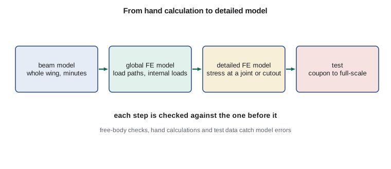
Aircraft programs use finite element models at two levels. The global finite element model, often called the GFEM, represents the whole airframe or a major component with relatively coarse elements: shell elements for skins and spar webs, beam or rod elements for stringers and spar caps, and simple representations of ribs and frames. Its job is to find the internal loads: how the external loads from the loads report travel through the structure, how much each spar, panel and fitting carries. It is run for hundreds or thousands of load cases, so it must be fast and robust.
Detailed finite element models, or DFEMs, zoom in on regions where the global model is too coarse to give stresses: a fitting, a cutout corner, a joint, a doubler around a door. They use fine meshes of shell or solid elements and take their boundary loads from the global model. A detailed model of the Tern's main landing gear attachment, for example, might have more elements than the whole global wing model. Between them, the two levels give the engineer internal loads everywhere and accurate stresses where it matters.
Choosing elements
Element choice follows the physics. Thin skins and webs, which carry membrane and bending loads, are modelled with shell elements. Stringers and spar caps are modelled as beam elements, which carry axial load and bending, or as rod elements if only axial load matters; they are usually offset from the skin to their true centroid so that the panel's bending stiffness is right. Fittings and lugs, which have real three-dimensional stress states, need solid elements. Fasteners are often represented by spring elements whose stiffness comes from test data, because the load sharing in a bolted joint depends on fastener flexibility. Mass elements carry the weight of fuel, systems and equipment for inertia loads and dynamic analysis.
Several modelling decisions have large effects on results. How the wing is attached to the fuselage, fixed or flexible, changes the root stresses. Whether buckled skins are given reduced stiffness changes how load shares between skin and stringers. How cutouts are represented changes the stresses around them. Each of these is a choice the engineer must justify and document. A model is a theory about how the structure behaves, and like any theory it must be tested.
Verification: is the model solving the equations correctly?
Verification asks whether the model is a correct solution of the mathematics it represents. The first checks are free-body checks: the reaction forces at the supports must balance the applied loads exactly, and the internal loads cut at any section must equal the shear force, bending moment and torque from the loads report at that section. A wing model whose root reactions do not match the integrated air and inertia loads has an error in its loads, its supports or its units, and no stress from it can be trusted. Next comes a check against hand calculations like those in Lessons 3 to 9. The stresses in the covers near mid-span, where beam theory is reliable, should match the idealized model closely. Finally, mesh convergence: refining the mesh in critical areas should change the results by only a few percent. If it does not converge, as at a sharp re-entrant corner where the theoretical stress is infinite, the engineer must recognize a singularity and use a different approach, such as a stress at a defined distance, a fatigue method based on nominal stress, or a detailed model with the real fillet radius.
Validation: is the model representing the real structure?
Validation asks whether the model represents the real aircraft. It comes from tests. Strain gauges on test articles, from components to the full-scale static test airframe, are compared with predicted strains. Deflections are measured and compared. Where the model disagrees, the engineer finds out why and corrects it, and the correlated model is then used for certification analyses. The rules allow analysis to be used for showing strength only where the method has been shown to be reliable for that kind of structure, which in practice means correlated with tests.
The standards and guidelines that support this work include the ASME guide on verification and validation in computational solid mechanics, which you met in MEC-450, and industry benchmark collections such as those published by NAFEMS. Many companies also have internal standards for element types, mesh density, fastener stiffness and documentation, refined over many programs.
A beam model as a first check
Before the global model exists, a simple beam model of the wing can check the hand calculations and give stiffness for aeroelastic work. The program below models one Tern Block 2 wing as a cantilever beam, with its bending stiffness taken from the idealized root section of Lesson 6 and scaled with the cube of the local chord, under the 1 g net loading of Lesson 1. It compares the finite element tip deflection with a direct numerical integration of the bending moment.
# A beam finite element model of the Tern Block 2 wing, checked against a hand integration
import math
E = 71700.0e6                       # Pa
s_half, cr, ct = 8.5, 2.27, 1.02
I_root = 209.3e-6                   # m4, from the idealized root box (Lesson 6)
chord = lambda y: cr + (ct - cr) * y / s_half
EI = lambda y: E * I_root * (chord(y) / cr) ** 3        # depth and width both scale with chord
def q_net(y):                       # N/m at 1 g: Schrenk lift minus wing and fuel weight (Lesson 1 shapes)
    W = 6500 * 9.81; area = (cr + ct) / 2 * s_half
    lift = 0.5 * (W / 2 * chord(y) / area + 4 * (W / 2) / (math.pi * s_half) * math.sqrt(max(0.0, 1 - (y / s_half) ** 2)))
    wing = 350 * 9.81 * chord(y) / area
    fuel = 550 * 9.81 / (0.6 * s_half) if y < 0.6 * s_half else 0.0
    return lift - wing - fuel
def solve(K, F):
    n = len(F); K = [row[:] for row in K]; F = F[:]
    for i in range(n):
        p = max(range(i, n), key=lambda r: abs(K[r][i])); K[i], K[p] = K[p], K[i]; F[i], F[p] = F[p], F[i]
        for r in range(i + 1, n):
            f = K[r][i] / K[i][i]
            for c in range(i, n): K[r][c] -= f * K[i][c]
            F[r] -= f * F[i]
    x = [0.0] * n
    for i in range(n - 1, -1, -1):
        x[i] = (F[i] - sum(K[i][c] * x[c] for c in range(i + 1, n))) / K[i][i]
    return x
def fe_tip(ne):
    L = s_half / ne; nd = 2 * (ne + 1)
    K = [[0.0] * nd for _ in range(nd)]; F = [0.0] * nd
    for e in range(ne):
        ym = (e + 0.5) * L; k = EI(ym) / L ** 3
        ke = [[12, 6*L, -12, 6*L], [6*L, 4*L*L, -6*L, 2*L*L], [-12, -6*L, 12, -6*L], [6*L, 2*L*L, -6*L, 4*L*L]]
        # consistent load vector for the element, by 4-point Gauss quadrature
        fe = [0.0] * 4
        for xi, wt in ((-0.861136, 0.347855), (-0.339981, 0.652145), (0.339981, 0.652145), (0.861136, 0.347855)):
            s = (xi + 1) / 2; y = e * L + s * L
            N = [1 - 3*s*s + 2*s**3, L*(s - 2*s*s + s**3), 3*s*s - 2*s**3, L*(-s*s + s**3)]
            for i in range(4): fe[i] += N[i] * q_net(y) * wt * L / 2
        dofs = [2*e, 2*e + 1, 2*e + 2, 2*e + 3]
        for i in range(4):
            F[dofs[i]] += fe[i]
            for j in range(4): K[dofs[i]][dofs[j]] += k * ke[i][j]
    free = list(range(2, nd))                                     # root clamped: w = 0 and slope = 0
    x = solve([[K[i][j] for j in free] for i in free], [F[i] for i in free])
    return x[-2]
# hand check: integrate the bending moment, then M/EI twice from the root
N = 2000; dy = s_half / N; ys = [(i + 0.5) * dy for i in range(N)]
V = M = 0.0; Ms = [0.0] * N
for k in range(N - 1, -1, -1):
    V += q_net(ys[k]) * dy; M += V * dy; Ms[k] = M
slope = w = 0.0
for k in range(N):
    slope += Ms[k] / EI(ys[k]) * dy; w += slope * dy
print(f"Hand integration: 1 g root moment {Ms[0]/1000:.1f} kN m, tip deflection {w*1000:.1f} mm")
for ne in (1, 2, 4, 8, 16):
    print(f"   beam model with {ne:2d} elements: tip deflection {fe_tip(ne)*1000:6.1f} mm")
print(f"At limit load (3.09 g, aerodynamic and inertia loads scaled together) the tip rises about {3.09*w*1000:.0f} mm")Hand integration: 1 g root moment 90.2 kN m, tip deflection 157.9 mm beam model with 1 elements: tip deflection 289.7 mm beam model with 2 elements: tip deflection 184.1 mm beam model with 4 elements: tip deflection 161.7 mm beam model with 8 elements: tip deflection 158.9 mm beam model with 16 elements: tip deflection 158.5 mm At limit load (3.09 g, aerodynamic and inertia loads scaled together) the tip rises about 488 mm
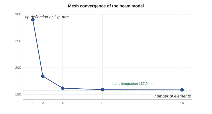
The hand integration gives a 1 g root moment of 90.2 kN m, consistent with the ultimate value of 421 kN m divided by 4.64, and a tip deflection of 158 mm. The finite element model with one element overestimates the deflection badly, at 290 mm, because a single element samples the stiffness at mid-span and cannot follow its variation along the wing. With four elements it is within 2.5 percent, and with sixteen it matches the integration to within 0.4 percent. At limit load the tip rises about half a metre, a figure the systems engineers need for routing the aileron controls and the wiring along the span.
The structures design review
Arjun's term ends with the preliminary design review of the Block 2 wing box. He presents the results of the course in the order an engineer would defend them. The loads: 421 kN m and 107 kN at the root at ultimate load, with 45 kN m of torque, from Schrenk loading with inertia relief and a check of the gust cases. The section: an idealized box with booms at caps and stringers and a shear centre near 35 percent chord. The upper cover: the first-pass layout failed as a stiffened panel, so the cover now has 2.5 mm skin and eight Z stringers with a margin of +0.31. The webs: shear flows near 200 N/mm, designed as tension-field webs with stiffeners. The lower cover: 2024-T3, thickness set by crack growth from a 2.5 mm flaw, with inspections every 16 500 flights. The control surfaces: carbon laminates, with a sixteen-ply aileron spar cap. The stiffness: a two-cell torsion box and a tip deflection of about half a metre at limit load.
Marcus adds the final step. Every analysis that supports certification will be checked by a second engineer and approved by a Design Approval Representative, an engineer authorized by Transport Canada to approve design data on its behalf. Analyses are documented so that someone who was not in the room can repeat them. The engineers who sign them take professional responsibility for their work, and the company's processes for checking and approval exist because, in aircraft structures, an unnoticed error in a model can stay hidden in a fleet for years.
Worked problem
Free-body check of a wing model
A global model of one Tern wing at the 3.09 g limit case reports a root shear of 71.0 kN and a root bending moment of 280 kN m. The loads report gives the net limit load on one wing as 71.3 kN acting 3.92 m from the root. Do the model results check?
Show solution
- Expected root shear: 71.3 kN. The model gives 71.0 kN, a difference of 0.4 percent.
- Expected root moment: \(71.3 \times 3.92 = 279.5\) kN m. The model gives 280 kN m.
- Both agree within 0.5 percent.
Answer: The model passes this check. A difference of several percent would point to missing loads, wrong mass data or a support problem, and would be investigated before any stresses were used.
Worked problem
Convergence and a singularity
A detailed model of a cover panel near a sharp corner of an access hole gives peak stresses of 310, 390, 480 and 590 MPa on successively halved meshes. What do the results suggest?
Show solution
- The peak stress keeps rising by more than 20 percent with every refinement and shows no sign of converging.
- This is the signature of a geometric singularity at a sharp corner.
Answer: The model must include the real corner radius, or the stress must be evaluated at a defined distance or by a nominal-stress method. Reporting 590 MPa, or any one of these values, would be meaningless.
Common mistakes
MistakeTrusting a model because it ran without errors.
InsteadCheck reactions, internal loads at sections and hand calculations before using any stress.
MistakeReading peak stresses at sharp corners or point loads.
InsteadThese are singularities; refine with real geometry or use another approach.
MistakeUsing a global model for local stresses at fittings.
InsteadGlobal models give internal loads; detailed models give local stresses.
MistakeSkipping documentation because the results look right.
InsteadCertification analyses must be repeatable and independently checked.
Summary and key terms
- Aircraft programs use global finite element models to find internal loads and detailed models for local stresses.
- Elements follow the physics: shells for skins and webs, offset beams for stringers, solids for fittings, springs for fasteners.
- Verification checks free-body balance, agreement with hand calculations and mesh convergence, and recognizes singularities.
- Validation correlates models with test strains and deflections.
- A beam model of the Tern wing converges to the hand result of 158 mm tip deflection at 1 g.
- Analyses are documented, independently checked and approved by authorized engineers.
- Global finite element model
- A coarse model of a whole airframe or component used to find internal loads.
- Detailed finite element model
- A refined local model used to find stresses at a fitting, joint or cutout.
- Free-body check
- A check that model reactions and internal loads balance the applied loads.
- Mesh convergence
- The behaviour of results as the mesh is refined; converged results change little.
- Singularity
- A point where the theoretical stress is infinite, such as a sharp re-entrant corner.
- Validation
- Showing by test comparison that a model represents the real structure.
Practice problems
Work each problem on paper first, then reveal the answer to check.
What should the sum of the root reactions of a wing model equal?
Show answer
The total applied air and inertia loads on that wing for the load case.
Why are stringer beam elements offset from the skin?
Show answer
To place their stiffness at the true centroid, giving the right panel bending stiffness.
In the program, what is the error with two elements?
Show answer
184.1 against 157.9 mm, about 17 percent.
What element type suits a thick machined lug?
Show answer
Solid elements.
A stress keeps rising as the mesh is refined at a corner. What is happening?
Show answer
A singularity; the result will not converge without the real geometry.
Who approves certification analyses on behalf of the regulator?
Show answer
An authorized delegate engineer, after independent checking.
Lesson quiz · 5 questions
Score 60% or more to complete this lesson.
Create a free account to save your progress, take quizzes and earn a certificate.