
AERO-300 · Lesson 6 of 12 · 23 min
Thin airfoil theory
Before computers, aerodynamicists needed a way to predict an airfoil's lift and pitching moment from its shape with pencil and paper. Thin airfoil theory, developed by Max Munk and Hermann Glauert in the 1920s, provides it. It replaces the airfoil with a sheet of vortices along its camber line and chooses their strength so that the camber line is a streamline. The results are simple, surprisingly accurate below the stall and still the first tool an aerodynamicist reaches for. Arjun uses it to predict the zero-lift angle and pitching moment of the Block 2 sections before the panel method and tunnel tests confirm them.
The vortex sheet model
Imagine many small vortices placed side by side along a line. In the limit they form a vortex sheet, with strength \(\gamma(s)\) per unit length, so the circulation of a short piece \(ds\) is \(\gamma\,ds\). Across a vortex sheet the tangential velocity jumps by \(\gamma\): the flow just above moves faster than the flow just below. That is exactly what a lifting airfoil does to the flow, so a vortex sheet is a natural model for it. The total circulation, and therefore the lift, is the integral of \(\gamma\) along the sheet.
Thin airfoil theory makes three simplifications. The airfoil is thin and the angle of attack small, so thickness is ignored for the lift problem and the vortex sheet is placed on the chord line rather than on the camber line, while still requiring the flow to follow the camber line's slope. The flow is inviscid and incompressible. And the Kutta condition holds: the sheet strength is zero at the trailing edge, so the flow leaves it smoothly.
The condition that the camber line be a streamline says that, at every point, the velocity induced by the whole vortex sheet must cancel the component of the free stream normal to the camber line. For small angles that component is \(V_\infty(\alpha - dz/dx)\), where \(z(x)\) is the camber line. The result is an integral equation for \(\gamma\).
The symmetrical airfoil
For a symmetrical section the camber line is the chord itself, so \(dz/dx = 0\). Changing variables with \(x = \tfrac{c}{2}(1 - \cos\theta)\), which runs from the leading edge at \(\theta = 0\) to the trailing edge at \(\theta = \pi\), the solution that satisfies the Kutta condition is remarkably simple.
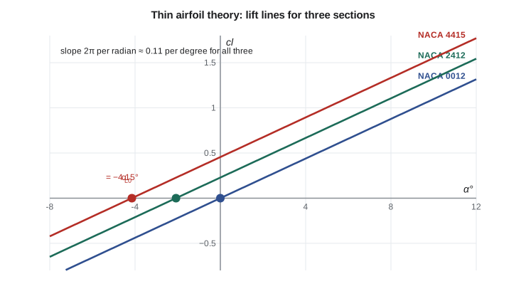
Three results follow. The lift coefficient is proportional to angle of attack with slope \(2\pi\) per radian, about 0.110 per degree. The lift acts at the quarter-chord point at every angle of attack, so the pitching moment about the quarter chord is zero; the quarter chord is both the centre of pressure and the aerodynamic centre. And the vortex strength becomes infinite at the leading edge. That singularity is not physical: a real airfoil has a rounded nose around which the flow accelerates to a high but finite speed, producing the suction peak. Thin airfoil theory gets the integrated lift right while being wrong in detail at the nose.
The cambered airfoil
With camber, the solution is written as a Fourier series. The vortex strength is the symmetrical airfoil's term plus a sine series whose coefficients depend on the camber line slope.
From these coefficients come the lift and moment. The lift slope is still \(2\pi\), but the line is shifted: the lift is zero not at \(\alpha = 0\) but at the zero-lift angle \(\alpha_{L0}\), which is negative for positive camber. The moment about the quarter chord is no longer zero but is a constant, independent of angle of attack, that depends only on the camber.
Because the moment about the quarter chord does not change with angle of attack, the quarter chord is still the aerodynamic centre: the point about which the moment is independent of lift. The centre of pressure, the point where the resultant lift acts, is not fixed. It moves forward as lift increases and travels far aft at low lift. That is why designers prefer to describe an airfoil by its lift and its moment about the aerodynamic centre rather than by a wandering centre of pressure.
# Thin airfoil theory for a cambered section by numerical Fourier integrals
import math
def slope(x, m, p):                    # camber-line slope dz/dx of a NACA four-digit section
    return 2 * m / p**2 * (p - x) if x < p else 2 * m / (1 - p)**2 * (p - x)
def thin(m, p, n=4000):
    I0 = I1 = I2 = 0.0
    for i in range(n):
        th = math.pi * (i + 0.5) / n; x = 0.5 * (1 - math.cos(th)); s = slope(x, m, p); d = math.pi / n
        I0 += s * d; I1 += s * math.cos(th) * d; I2 += s * math.cos(2 * th) * d
    aL0 = (I0 - I1) / math.pi            # zero-lift angle, rad
    A1, A2 = 2 * I1 / math.pi, 2 * I2 / math.pi
    cm = math.pi / 4 * (A2 - A1)         # moment about the quarter chord
    return aL0, A1, A2, cm
for name, m, p in [('NACA 0012', 0.0, 0.4), ('NACA 2412', 0.02, 0.4), ('NACA 4412', 0.04, 0.4), ('NACA 4415', 0.04, 0.4), ('NACA 6409', 0.06, 0.4)]:
    if m == 0: aL0, cm = 0.0, 0.0
    else: aL0, A1, A2, cm = thin(m, p)
    print(f"{name}: alpha_L0 = {math.degrees(aL0):6.2f} deg, cm_c/4 = {cm:7.4f}")
aL0, A1, A2, cm = thin(0.04, 0.4)
for a in (0, 2, 4, 6):
    cl = 2 * math.pi * (math.radians(a) - aL0)
    xcp = 0.25 - cm / cl
print(f"NACA 4415 at {a} deg: cl = {cl:.3f}, pressure acts at x/c = {xcp:.3f}")NACA 0012: alpha_L0 = 0.00 deg, cm_c/4 = 0.0000 NACA 2412: alpha_L0 = -2.08 deg, cm_c/4 = -0.0531 NACA 4412: alpha_L0 = -4.15 deg, cm_c/4 = -0.1062 NACA 4415: alpha_L0 = -4.15 deg, cm_c/4 = -0.1062 NACA 6409: alpha_L0 = -6.23 deg, cm_c/4 = -0.1594 NACA 4415 at 0 deg: cl = 0.456, pressure acts at x/c = 0.483 NACA 4415 at 2 deg: cl = 0.675, pressure acts at x/c = 0.407 NACA 4415 at 4 deg: cl = 0.894, pressure acts at x/c = 0.369 NACA 4415 at 6 deg: cl = 1.114, pressure acts at x/c = 0.345
The program evaluates the Fourier integrals numerically using the change of variable \(x = \tfrac{1}{2}(1 - \cos\theta)\). For the NACA 2412 it gives \(\alpha_{L0} = -2.08°\) and \(c_{m,c/4} = -0.053\), very close to the measured values of about \(-2.1°\) and \(-0.05\). Both results scale directly with the camber, so the 4 percent sections give twice these values: \(-4.15°\) and \(-0.106\). Thickness does not enter, so the NACA 4412 and 4415 have identical predictions. Measured values for the 4412 and 4415 are close to minus 4 degrees and between about minus 0.09 and minus 0.10 for the moment; the theory slightly overestimates the moment because the real boundary layer thickens toward the trailing edge and reduces the effective camber there.
The last lines show the centre of pressure of the NACA 4415 moving from 48 percent of chord at zero angle of attack to 34.5 percent at 6 degrees. If the section produced no lift at all, the moment would remain and the centre of pressure would be infinitely far aft, a reminder that it is a poor reference point.
What thin airfoil theory tells a designer
For the Block 2 wing, the theory gives three useful results. First, the zero-lift angle of minus 4.15 degrees means the wing can cruise at a small positive incidence, about zero degrees fuselage attitude with the wing set at a modest angle on the fuselage, which keeps the cabin level for passengers. Second, the quarter-chord moment of about minus 0.1 means a nose-down pitching moment that, at cruise dynamic pressure, amounts to about 5068 times 28 times 1.73 times 0.1, or nearly 25 kN·m, which the horizontal tail must balance with a download. That download costs drag, and it grows with camber, which is one reason the team did not choose a more highly cambered section. Third, the theory shows how to shape the camber line to get a desired result. Moving the maximum camber aft increases the moment; reflexing the rear of the camber line upward, as on some flying wings, can reduce the moment to zero at the cost of maximum lift.
The theory also shows how flaps work, which Lesson 12 develops. Deflecting a trailing-edge flap adds camber near the rear of the section, which changes \(\alpha_{L0}\) strongly because the integral weights the rear of the camber line heavily through the \((\cos\theta_0 - 1)\) factor. A small change in the trailing-edge region moves the zero-lift angle by much more than the same change near the nose.
Limits of the theory
Thin airfoil theory ignores thickness, so it misses the small increase in lift slope that thickness gives in inviscid flow and the decrease that the boundary layer causes in real flow. Measured lift slopes for typical sections fall between about 0.100 and 0.108 per degree, a few percent below \(2\pi\). It says nothing about maximum lift or stall, nothing about drag and nothing about the detailed pressure distribution near the leading edge. For those, the panel methods of Lesson 7 and the boundary-layer ideas of Lessons 10 and 11 are needed. Within its limits it remains astonishingly good, and its explanation of why camber shifts the lift line and creates a constant moment is the foundation of every later method.
Worked problem
Lift and moment of the root section
The NACA 4415 root section of the Block 2 wing has a chord of 2.27 m. At the approach condition, 52 m/s at sea level, it works at 5 degrees angle of attack. Use thin airfoil theory to find the section lift and the pitching moment about the quarter chord per unit span.
Show solution
- \(c_l = 2\pi(\alpha - \alpha_{L0}) = 2\pi\times(5 + 4.15)\times\pi/180 = 1.003\).
- \(q = 0.5\times 1.225\times 52^2 = 1656\ \text{Pa}\).
- Lift per unit span: \(L' = q c\,c_l = 1656\times 2.27\times 1.003 = 3771\ \text{N/m}\).
- Moment per unit span: \(M' = q c^2 c_{m} = 1656\times 2.27^2\times(-0.106) = -905\ \text{N·m/m}\), nose down.
Answer: Each metre of the root produces about 3.8 kN of lift and a nose-down moment of about 0.9 kN·m. Tunnel data would give a slightly lower lift coefficient, about 0.96, because the real lift slope is a little below \(2\pi\).
Worked problem
Finding the zero-lift angle from data
A tunnel test of a section gives \(c_l = 0.25\) at 0° and \(c_l = 0.88\) at 6°. Find the measured lift slope and zero-lift angle, and compare them with thin airfoil theory.
Show solution
- Slope: \((0.88 - 0.25)/6 = 0.105\) per degree, about 95.5 percent of \(2\pi\) per radian (0.1097 per degree).
- Zero-lift angle: \(0 - 0.25/0.105 = -2.38°\).
Answer: The slope is typical of a real section. A zero-lift angle of minus 2.4 degrees suggests a camber of a little over 2 percent if the camber line is of the four-digit type.
Common mistakes
MistakeAssuming the centre of pressure stays at the quarter chord on a cambered section.
InsteadOnly the aerodynamic centre is fixed. The centre of pressure moves with lift and goes far aft at low lift.
MistakeExpecting thickness to change the thin-airfoil zero-lift angle or moment.
InsteadThin airfoil theory ignores thickness. The NACA 4412 and 4415 have the same predicted values.
MistakeForgetting to convert degrees to radians in c_l = 2π(α − α_L0).
InsteadThe slope 2π is per radian. In degrees the slope is about 0.11.
MistakeUsing thin airfoil theory to predict maximum lift.
InsteadThe theory is linear and inviscid. It cannot predict separation or stall.
Summary and key terms
- Thin airfoil theory models a section as a vortex sheet on the chord line whose strength makes the camber line a streamline and satisfies the Kutta condition.
- For a symmetrical section c_l = 2πα and the lift acts at the quarter chord.
- For a cambered section the lift line is shifted to the zero-lift angle α_L0 and there is a constant moment about the quarter chord, which is the aerodynamic centre.
- Both are found from Fourier integrals of the camber line slope.
- The theory predicts lift and moment well below the stall but not drag, maximum lift or detailed nose pressures.
- Vortex sheet
- A continuous distribution of vorticity along a line or surface.
- Zero-lift angle
- The angle of attack at which a section produces no lift.
- Aerodynamic centre
- The point about which the pitching moment does not change with lift.
- Centre of pressure
- The point where the resultant aerodynamic force acts, which moves with lift.
- Lift slope
- The rate of change of lift coefficient with angle of attack.
- Fourier coefficients
- The coefficients A0, A1, A2 that describe the vortex sheet strength in thin airfoil theory.
- Reflex camber
- Upward curvature of the rear camber line used to reduce the pitching moment.
Practice problems
Work each problem on paper first, then reveal the answer to check.
A symmetrical section is at 4°. Find c_l from thin airfoil theory.
Show answer
c_l = 2π × 4 × π/180 = 0.439.
A section has α_L0 = −3°. What c_l does thin airfoil theory give at 2°?
Show answer
c_l = 2π × 5 × π/180 = 0.548.
Why does a cambered airfoil need a tail download in cruise even when the wing lift acts near the centre of gravity?
Show answer
The constant nose-down moment about the aerodynamic centre must be balanced.
In the program, change the camber position of the NACA 4415 from 0.4 to 0.2 (a NACA 4215 camber line). What happens to the moment?
Show answer
Moving the camber forward reduces the size of the quarter-chord moment to about −0.074 and the zero-lift angle to about −3.6°.
A section has c_m,c/4 = −0.08 and c_l = 0.5. Where is the centre of pressure?
Show answer
x_cp/c = 0.25 + 0.08/0.5 = 0.41.
Why does a flap at the trailing edge change α_L0 much more than the same deflection near the leading edge?
Show answer
The integral for α_L0 weights the camber slope by (1 − cos θ), which is largest near the trailing edge.
Lesson quiz · 5 questions
Score 60% or more to complete this lesson.
Create a free account to save your progress, take quizzes and earn a certificate.